Method and apparatus for mapping the underground soil

a technology of underground soil and mapping method, which is applied in the field of geophysics, mining and security, can solve the problems of interfering electromagnetic waves with soil, and is considered noise, and achieve the effect of maximizing the signal-to-noise ratio

Inactive Publication Date: 2016-06-30
SUHAMI AVRAHAM
View PDF0 Cites 31 Cited by
  • Summary
  • Abstract
  • Description
  • Claims
  • Application Information

AI Technical Summary

Benefits of technology

[0011]The invention describes a system for mapping the underground soil, in terms of its conductance and permittivity using electromagnetic antennas to measure elapsed time and attenuation of straight-line rays between transmitters and receivers at optimal frequencies that maximize signal-to-noise-ratio between said antennas.

Problems solved by technology

Any interaction of the transmitted electromagnetic wave with the soil, is considered noise, as it takes time.

Method used


Image

  • Method and apparatus for mapping the underground soil
  • Method and apparatus for mapping the underground soil
  • Method and apparatus for mapping the underground soil

Examples


Embodiment Construction

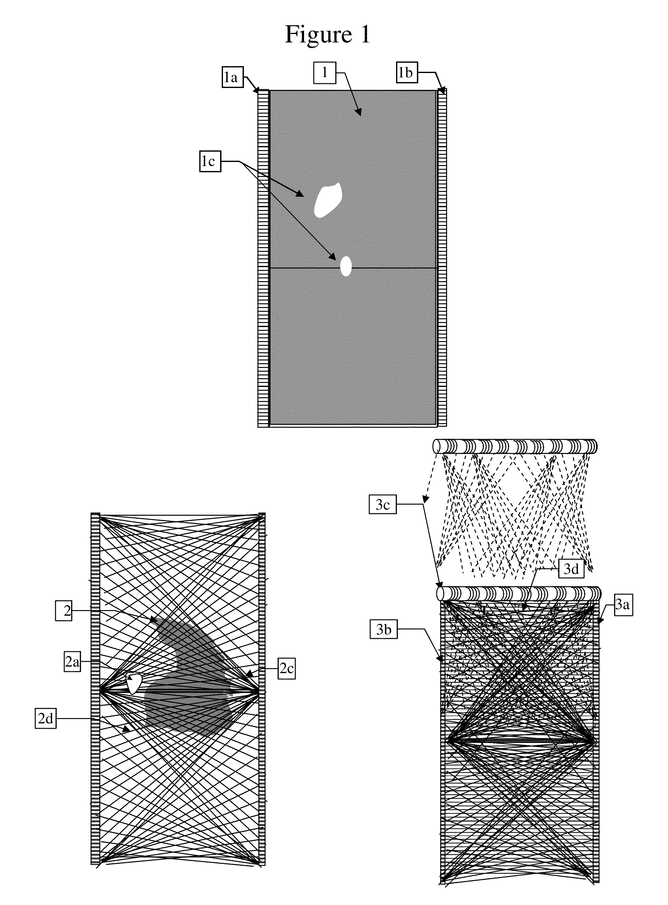
[0039]FIG. 1 illustrates 3 modes of imaging the underground soil with electromagnetic waves. The first mode is applicable specifically to non-magnetic soils characterized by relatively uniform or slowly changing conductivity and permittivity, with air cavities inside. Imaging cross sections of these kinds of soils is straightforward, by measuring straight-line transmission of electromagnetic waves along parallel lines 1 from near surface to practically any depth, assuming that attenuation doesn't change much, but when crossing air cavities 1c. The air cavities are spotted as decreased attenuation of straight-line transmission between a transmitter and a receiver at the same depth, within tubes 1a, 1b inserted into the soil.

[0040]The second mode illustrated in FIG. 1 pertains to soils with large changes in the soil characteristics of conductivity, permittivity and permeability such that the straight line attenuation between two points at the same depth cannot be attributed only to an...


PUM


Abstract

The invention describes a method and system, for mapping non-magnetic soils in terms of their local permittivity and velocity of the traversing electromagnetic waves, by measuring the straight-line attenuation and elapsed time between transmitters and receivers located within tubes inserted into the soil.

Description

FIELD OF THE INVENTION[0001]This invention relates to the fields of geophysics, mining and securityBACKGROUND[0002]Mapping the soil underneath ground is of great interest in many areas. Before constructing anything above ground, houses, roads and bridges, it is essential to know what is beneath them. Mapping the deep soil characteristics including its compressibility, its conductivity, its moisture content and the presence of voids and air cavities whether natural or man-made, are parts of the general construction requirements.[0003]The general theory of tomography is well known (see for example Principles of Computerized Tomographic Imaging, IEEE Press 1988—by A. C. Kak and Malcolm Stanley). In principle mapping what is inside an object, is nothing more than solving a set of (n) independent equations of (n) unknowns, part of high school algebra. In the case of a substantially round object, for example a cross section of the human body, the number of independent equations may be est...

Claims


Application Information

Patent Timeline
Patent Type & Authority Applications(United States)
IPC IPC(8): G01V3/30
CPCG01V3/30
Inventor SUHAMI, AVRAHAM
Owner SUHAMI AVRAHAM
Why Eureka
Try Eureka