Device and method for making weather observations using infrared spectral radiometry

a technology of infrared spectral radiometry and instruments, applied in the field of atmospheric measurements, can solve problems such as substantial errors in the assigned wind velocity vector, and achieve the effects of reducing the required size of the infrared spectrometer, reducing operating temperature, and reducing siz

Active Publication Date: 2016-06-30
BAE SYST INFORMATION & ELECTRONICS SYST INTERGRATION INC
View PDF2 Cites 23 Cited by
  • Summary
  • Abstract
  • Description
  • Claims
  • Application Information

AI Technical Summary

Benefits of technology

[0012]Another object of the invention is to employ an innovative compact spectral disperser element, as a modification of the optical design of each instrument, thereby enabling an instrument of much smaller size than those of current designs, in order to reduce the associated mass and cost of each satellite forming a constellation.
[0013]Another object of the invention is to employ an array of HgCdTe avalanche photodiodes, which enable the low-noise observation of spectral radiances at higher detector operating temperatures than present-day infrared detector technology, substantially reducing the cooling (as well as the electrical power) requirements of the spectral instrument.
[0018]While the concept of using spectrally resolved measurements, at separate times, for make wind measurements is generally know, such measurements—according to conventional prior art techniques—have only been envisioned with radiance measurements from a single sensor (at different times) hosted aboard a satellite in a geostationary orbit. The present invention is directed at making such measurements, from multiple low-cost instruments orbiting in a low-earth orbit (where each sensor and spacecraft can be dramatically smaller in size and installed at a lower cost), but where each sensor makes only one measurement of the spectral radiance field.
[0021]Another object of the invention, besides the measurement method using a plurality of micro-satellites, are methods to allow the spectrometer payload to have small enough size, mass, and power requirements so that hey can readily fit on and orbit in a micro-satellite. Given current micro-satellite technology, approximate numbers for the maximum power demand are typically less than 50 Watts and the mass for the sensor less than 110 pounds (50 kg), and generally less than 33 pounds (15 kg). In order to achieve this, the present invention includes a modified spectrometer design that allows operation ata relatively high spectrometer operating temperature—which allows much less cooling to be employed, thereby saving mass and power. This spectrometer design is derived from one used for HyLITE and Scotland (Airborne Hyperspectral Imaging Programs for the government), but is modifying and applying the design to solve a resource / minimization problem in a unique way.
[0023]The present invention also includes an improved spectrometer optical concept that minimizes the required size of the infrared spectrometer without adding in components or design features that would require a much lower operating temperature. More specifically, the present invention includes a refractive element, added to a conventional Offner spectrometer, which is proximate to the grating and slightly impacts the thermal load, but also provides important size reduction.

Problems solved by technology

Wherefore, it is the object of the present invention to overcome the above mentioned shortcomings and drawbacks associated with the prior art, More specifically, 1) present infrared hyperspectral methods observe the atmosphere too infrequently, and at too coarse a spatial resolution in order to resolve rapidly changing and fine-scale weather patterns, and 2) present multi-spectral (not hyperspectral) motion-vector winds methods used from GEO orbit lack sufficient information on the height or altitude in the observed wind-tracer features above the ground, resulting in substantial errors in the assigned wind velocity vector.

Method used


Image

  • Device and method for making weather observations using infrared spectral radiometry
  • Device and method for making weather observations using infrared spectral radiometry
  • Device and method for making weather observations using infrared spectral radiometry

Examples


Embodiment Construction

[0051]The present invention may be understood by reference to the following detailed description, which should be read in conjunction with the appended drawings. It is to be appreciated that the following detailed description of various embodiments is by way of example only and is not meant to limit, in any way, the scope of the present invention.

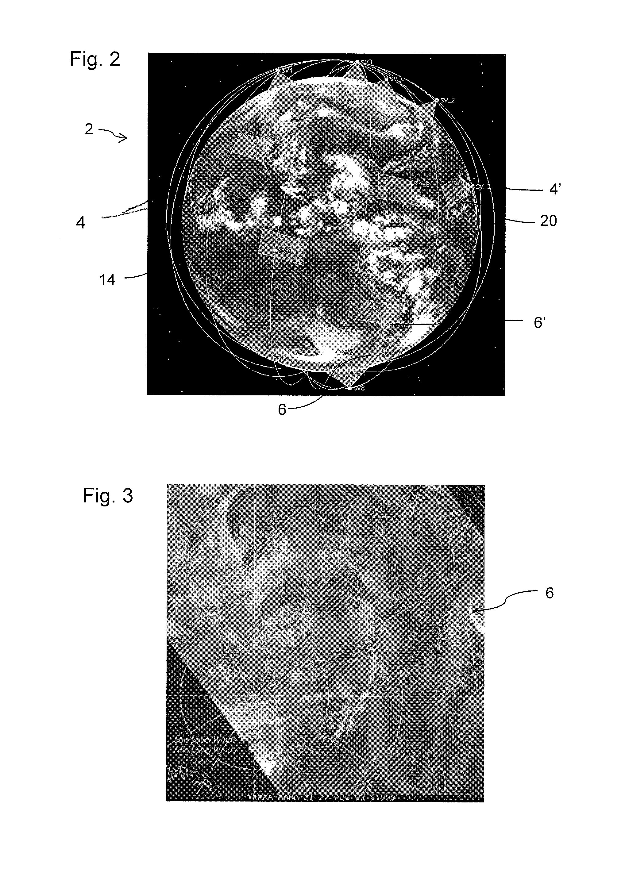
[0052]Turning now to FIG. 2, a brief description concerning the various satellite systems and constellations 4, of the system 2 of the present invention will now be briefly discussed. FIG. 1B is a schematic drawing showing temperature and humidity sounding constellations 4, according to one embodiment of the invention. A first constellation 4 comprises at least eight different separate micro-satellite 4′, which provide observations of the same area every 90 minutes. A second constellation 6, comprises at least three separate micro-satellite 6′ which provide three similar but separate observations of a region and each of the observations are...


PUM


Abstract

A method of weather observations by a constellation comprises at least a first duster of three micro-satellites each orbiting around earth, and each micro-satellites comprises a spectrometer. Orbiting the three micro-satellites of the first duster around the earth in three separate orbits offset with respect to one another. Staggering the three micro-satellites with respect to one another as they orbit. Selecting the offset and the staggering, of each of the three micro-satellites with respect to one another, so that each one of the three micro-satellites have a substantially identical viewing area as each one of the three micro-satellites orbits around the earth. Sequentially collecting observations, from each of the three micro-satellites, as the micro-satellites orbit around the earth and observe substantially identical viewing areas, to separately gather atmospheric measurements and provide critical data for weather forecasting by infrared temperature and humidity soundings and motion vector winds of the earth.

Description

CROSS REFERENCE TO RELATED APPLICATIONS / PRIORITY[0001]This application claims priority benefits of U.S. Application Ser. No. 62 / 098,468 filed Dec. 31, 2014, which disclosure is hereby incorporated by reference in its entirety.FIELD OF THE INVENTION[0002]The present invention relates to a weather observation system and method incorporating the same. More particularly, the invention relates to atmospheric measurements for the purpose of providing critical data for weather forecasting by means of infrared temperature and humidity soundings and motion vector winds.BACKGROUND OF THE INVENTION[0003]Numerous studies illustrating the substantial potential for weather forecast improvements due to rapidly refreshed high spectral resolution infrared spectral sounding measurements have been conducted. In general, these benefits are the result of comparative measurements that show the development of unstable atmospheric conditions or that reveal motion of the atmosphere at different altitudes.[0...

Claims


Application Information

Patent Timeline
Patent Type & Authority Applications(United States)
IPC IPC(8): G01W1/10G01J3/02
CPCG01J3/02G01W1/10G01J3/0208G01J3/021G01J3/0256G01J3/0286G01J3/0291G01J3/18G01J3/2803G01J5/007G01J5/60
Inventor MASCHHOFF, KEVIN R.POLIZOTTI, JOHN J.PERRON, GERARD M.
Owner BAE SYST INFORMATION & ELECTRONICS SYST INTERGRATION INC
Why Eureka
Try Eureka