System and method for expansion of field of view in a vision system

a vision system and camera lens technology, applied in the field of vision systems, can solve the problems of reducing affecting the field of view of a single reader, and affecting the accuracy of the image, so as to reduce the need for resolution, increase the resolution, and be convenient to install and use.

Active Publication Date: 2016-06-30
COGNEX CORP
View PDF0 Cites 16 Cited by
  • Summary
  • Abstract
  • Description
  • Claims
  • Application Information

AI Technical Summary

Benefits of technology

[0007]This invention overcomes disadvantages of the prior art by providing a system and method for expanding the field of view of a scene imaged by a vision system camera assembly having an image sensor defining an image plane. The system and method desirably expands the field of view (FOV) of an ID reader or other vision system arrangement in the widthwise direction with respect to a moving line in a manner that does not decrease needed resolution. The system and method also allows use of a conventional sensor and camera optics and is generally straightforward to install and use. Moreover, the system and method desirably increases resolution in the height/line-motion direction. Also desirably, the system and method can be adapt

Problems solved by technology

Thus, the field of view of a single reader, particularly in with widthwise direction (perpendicular to line motion) is often limited.
Where an object and/or the line is relatively wide, the lens and sensor of a single ID reader may not have sufficient field of view in the widthwise direction to cover the entire width of the line while maintaining needed resolution for accurate imaging and decoding of IDs.
Failure to image the full width can cause the reader to miss IDs that are outside of the field of view.
This is often an expensive solution as it requires additional hardware and optics.
However, this arrangement can also increase costs as it requires more specialized hardware and generally increases complexity.
However, the approach again entails additional cost through the use of less-conven

Method used


Image

  • System and method for expansion of field of view in a vision system
  • System and method for expansion of field of view in a vision system
  • System and method for expansion of field of view in a vision system

Examples


Embodiment Construction

I. FOVE General Overview and Operation

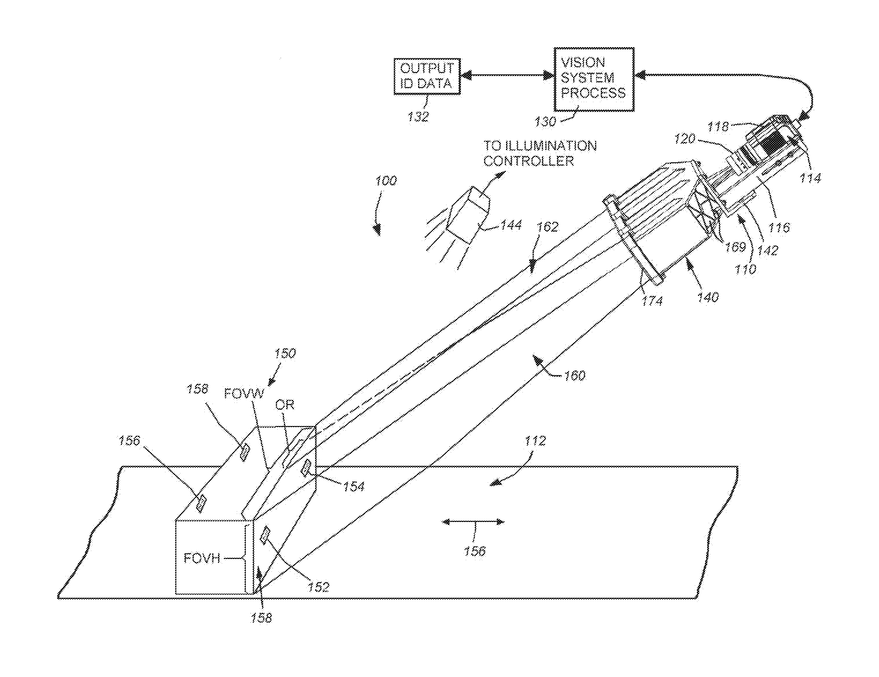
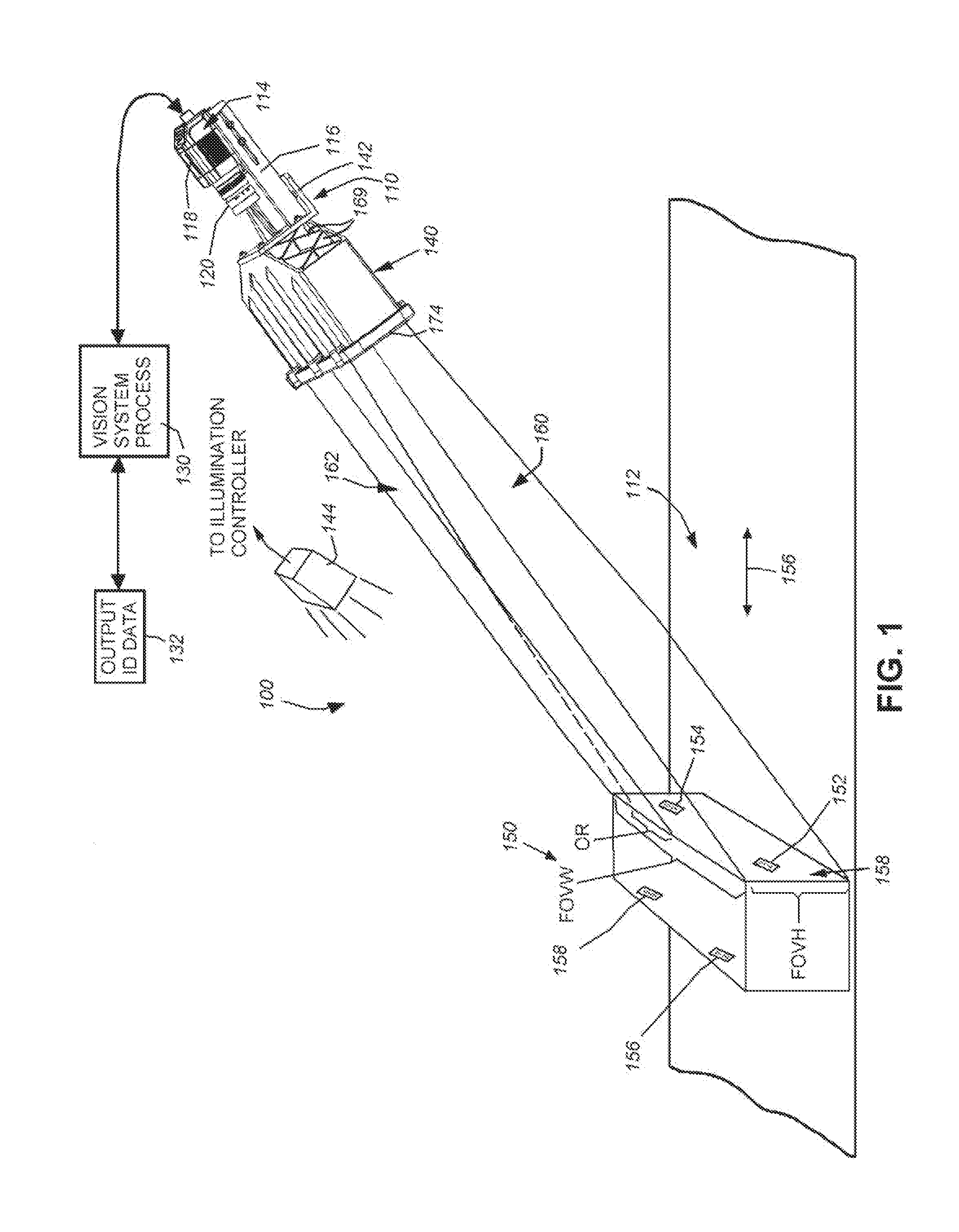
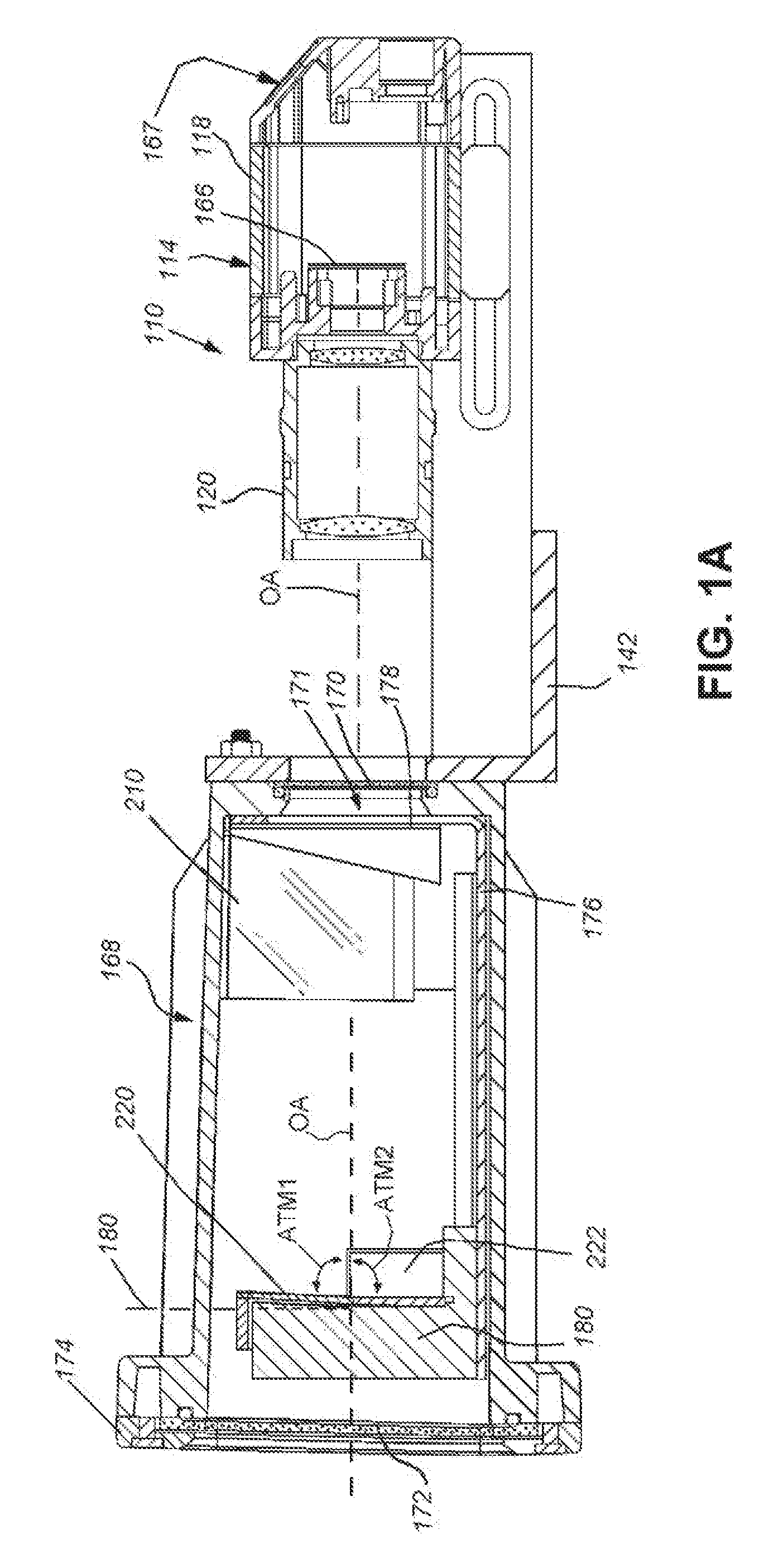
[0048]FIG. 1 shows a vision system arrangement 100 in which a vision system or ID reader assembly 110 oriented at an acute angle with respect to a moving line represented by a conveyor 112. The vision system 110 includes a camera assembly 114 adjustably mounted in a frame 116. The camera assembly includes the camera base 118 and a lens 120. A variety of camera implementations can be employed in alternate embodiments. In an embodiment, the base 118 includes an internal sensor (described below), having a pixel array for acquiring grayscale of color image data. The size of the array is highly variable. For example, the array can be a conventional rectangular (roughly square) array having a size of 1024×768 pixels. In alternate embodiments, other array sizes, including, but not limited to, 2048×384 or 2048×768 pixels can be employed. The camera base 118 can include an internal vision processor and ID (barcode) decoding circuit. Alternatively, the ca...


PUM


Abstract

This invention provides a field of view expander (FOVE) removably attached to a vision system camera having an image sensor defining an image plane. In an embodiment the FOVE includes first and second mirrors that transmit light from a scene in respective first and second partial fields of view along first and second optical axes. Third and fourth mirrors respectively receive reflected light from the first and second mirrors. The third and fourth mirrors reflect the received light onto the image plane in a first strip and a second strip adjacent to the first strip. The first and second optical axes are approximately parallel and a first focused optical path length between the scene and the image plane and a second focused optical path between the image plane and the scene are approximately equal in length. The optical path can be rotated at a right angle in embodiments.

Description

RELATED APPLICATION[0001]This application is a continuation-in-part of U.S. patent application Ser. No. 14 / 680,143, filed Apr. 7, 2015, entitled SYSTEM AND METHOD FOR EXPANSION OF FIELD OF VIEW IN A VISION SYSTEM, which is a continuation of co-pending U.S. patent application Ser. No. 13 / 645,241, filed Oct. 4, 2012, entitled SYSTEM AND METHOD FOR EXPANSION OF FIELD OF VIEW IN A VISION SYSTEM, now U.S. Pat. No. 9,027,838, issued May 12, 2015, which is a continuation-in-part of co-pending U.S. patent application Ser. No. 13 / 367,141, filed Feb. 6, 2012, entitled SYSTEM AND METHOD FOR EXPANSION OF FIELD OF VIEW IN A VISION SYSTEM, now U.S. Pat. No. 8,646,690, issued Feb. 11, 2014, the entire disclosure of each of which applications is herein incorporated by reference.FIELD OF THE INVENTION[0002]This invention relates to vision systems, and more particularly to systems and methods for expanding the field of view of a vision system camera lens.BACKGROUND OF THE INVENTION[0003]Vision system...

Claims


Application Information

Patent Timeline
IPC IPC(8): G06K7/10H04N5/225
CPCH04N5/225G06K7/10722G02B26/105G02B26/12G02B27/1066G02B27/143G03B17/565G06K7/10603H04N23/00G02B17/023G02B17/06G02B27/14
Inventor NUNNINK, LAURENSGERST, III, CARL W.EQUITZ, WILLIAMENGLE, MATTHEW D.
Owner COGNEX CORP
Why Eureka
Try Eureka