
Organic light emitting diode display device and driving method thereof

a light-emitting diode and display device technology, applied in the direction of instruments, computing, electric digital data processing, etc., can solve the problems of low light emission efficiency, low brightness and high power consumption, and serious problems of pdps, so as to reduce the number of memories, accurately sense the operation voltage, and accurately control the current flowing

Active Publication Date: 2016-06-30
LG DISPLAY CO LTD
View PDF4 Cites 39 Cited by
  • Summary
  • Abstract
  • Description
  • Claims
  • Application Information

AI Technical Summary

Benefits of technology

The patent text describes an organic light emitting diode display device and its driving method that can accurately control the current flowing through the diode by detecting the threshold voltage of the driving transistor. It also minimizes the mobility component of the driving transistor through a mobility compensation of the driving switch. Additionally, it reduces the number of memories by sensing the operation voltage of the diode using a pixel structure and removes a separate memory used to store the sensed mobility value of the driving switch. The device also prevents data communication errors by receiving sensed data using internal clocks with different phases. Overall, the patent aims to provide an improved display device with improved accuracy and efficiency.

Problems solved by technology

However, the PDPs have serious problems such as low light emission efficiency, low brightness and high power consumption.
However, the thin film transistor LCD devices have disadvantages such as a narrow viewing angle and a low response time, because of being non-luminous devices.
However, it is difficult to detect the deterioration degree of the organic light emitting diode.
Due to this, errors can be generated in the sensed data and the compensation data.
However, the delay control method cannot sense real-time data (or variations thereof) generated at a real (or normal) operation, not an initial setup operation.

Method used


Image

  • Organic light emitting diode display device and driving method thereof
  • Organic light emitting diode display device and driving method thereof
  • Organic light emitting diode display device and driving method thereof

Examples


Embodiment Construction

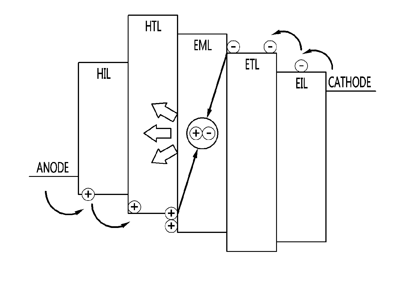
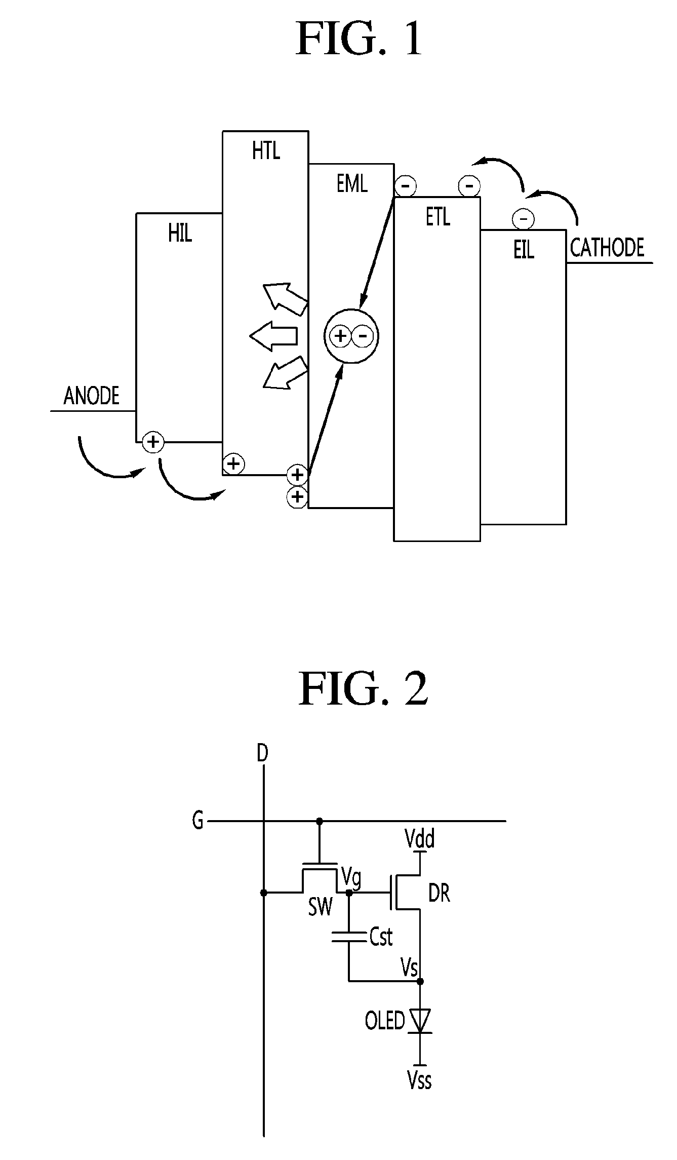
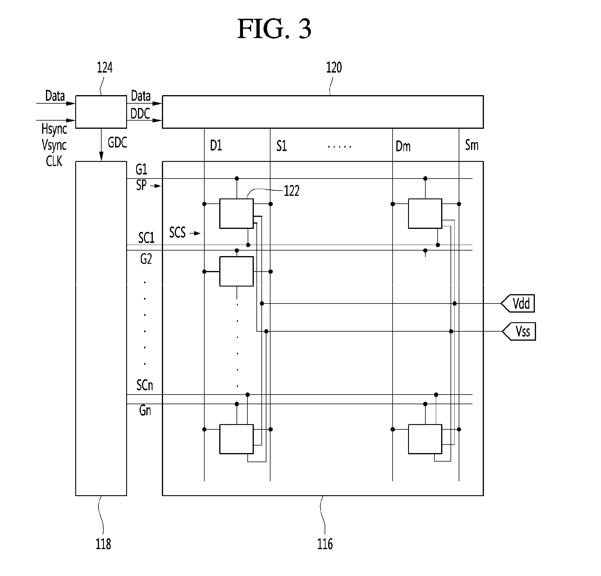
[0042]Reference will now be made in detail to an OLED display device and a driving method thereof in accordance with the embodiments of the present disclosure, examples of which are illustrated in the accompanying drawings. These embodiments introduced hereinafter are provided as examples in order to convey their spirits to the ordinary skilled person in the art. Therefore, these embodiments might be embodied in a different shape, so are not limited to these embodiments described here. In the drawings, the size, thickness and so on of a device can be exaggerated for convenience of explanation. Wherever possible, the same reference numbers will be used throughout this disclosure including the drawings to refer to the same or like parts.

[0043]Advantages and features of the present disclosure, and implementation methods thereof will be clarified through the following embodiments described with reference to the accompanying drawings. These embodiments introduced hereinafter are provided...


PUM


Abstract

An organic light emitting diode display device according to an embodiment includes pixels each configured with an organic light emitting diode and a driving switch used to control a current flowing through the organic light emitting diode. The organic light emitting diode display device compensates a deterioration property of the organic light emitting diode after properties of the driving switch is compensated. As such, the deterioration property of the organic light emitting diode can be maximally reflected to a sensing data. In accordance therewith, the deterioration property of the organic light emitting diode can be accurately compensated.

Description

[0001]The present application claims priority under 35 U.S.C. §119(a) of Korean Patent Application No. 10-2014-0192089 filed on Dec. 29, 2014, which is hereby incorporated by reference in its entirety.BACKGROUND OF THE INVENTION[0002]1. Field of the Disclosure[0003]The present application relates to an organic light emitting diode display device and a driving method thereof.[0004]2. Description of the Related Art[0005]Recently, a variety of flat panel display (FPD) devices adapted to reduce weight and volume corresponding to disadvantages of cathode ray tube (CRT) are being developed. The flat panel display devices include liquid crystal display (LCD) devices, field emission display (FED) devices, plasma display panels (PDPs), electroluminescence devices and so on.[0006]The PDPs have advantages such as simple structure, simple manufacture procedure, lightness and thinness, and are easy to provide a large-sized screen. In view of these points, the PDPs attract public attention. Howev...

Claims


Application Information

Patent Timeline
Patent Type & Authority Applications(United States)
IPC IPC(8): G09G3/32
CPCG09G2310/08G09G3/3258G09G2300/0861G09G2320/0295G09G2320/045G09G3/3233H10K59/84H10K59/00H10K71/00
Inventor KIM, TAE GUNGKIM, JUNG HYEON
Owner LG DISPLAY CO LTD
Learn More