CNC dual-spindle transmission device

Active Publication Date: 2016-07-07
BAIZHENG INNOVATION TECHNOLOGY CO LTD
View PDF7 Cites 28 Cited by
  • Summary
  • Abstract
  • Description
  • Claims
  • Application Information

AI Technical Summary

Benefits of technology

[0012]The efficacy of the present invention is that the second slide seat extends in the left-right direction across the first slide seat and is, together with but spaced from the first slide seat, slidably mounted to the linear rails so as to respectively receive the first and second spindles to mount thereto and also be respectively driven by the first and second power units to move in the up-down direction, whereby the linear rails used can be of a number that is minimum but still enable the slidable arrangement of two slide seats in a manner of being independently drivable for sliding motion so that the size of the machine can be effectively reduced to save cost and also, doubling of efficiency of the machining time and machining of both large a

Problems solved by technology

This also overcomes the drawback of the conventional dual-spindle C-shaped vertical machining center that the two spindles are both mounted on a spindle head slide seat and are thus unitarily combined with t

Method used


Image

  • CNC dual-spindle transmission device
  • CNC dual-spindle transmission device
  • CNC dual-spindle transmission device

Examples


first embodiment

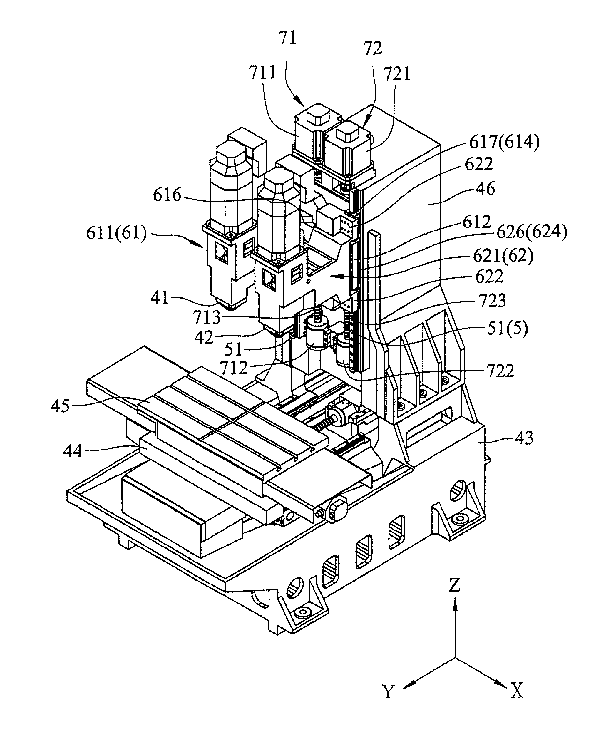
[0032]Referring to FIGS. 6, 7, and 8, a computer numerical control (CNC) dual-spindle transmission device according to the present invention is installable in a CNC dual-spindle vertical machining center in such a way that a first spindle 41 and a second spindle 42 of the CNC dual-spindle vertical machining center are mounted thereto in a manner of being erected upright in an up-down direction Z. The CNC dual-spindle vertical machining center further comprises a base 43, a saddle 44, a machining table 45, and a vertical column 46. The saddle 44 is mounted on the base 43 in a manner of being reciprocally movable in a front-rear direction Y. The machining table 45 is mounted on the saddle 44 in a manner of being reciprocally movable in a left-right direction X. The vertical column 46 is erected upright in the up-down direction Z at a rear portion of the base 43. The first spindle 41 and the second spindle 42 both have a lower end for gripping and holding a tool (not shown) and both ar...

second embodiment

[0043]Referring to FIGS. 11, 12, and 13, a CNC dual-spindle transmission device according to the present invention is installable on a CNC dual-spindle horizontal machining center in such a way that a first spindle 41 and a second spindle 42 of the CNC dual-spindle horizontal machining center are mounted thereto to be arranged in a front-rear direction Y. The CNC dual-spindle horizontal machining center further comprises a base 43, a saddle 44, a machining table 45, and a vertical column 46. The saddle 44 is mounted on the base 43 in a manner of being reciprocally movable in a front-rear direction Y. The machining table 45 is mounted on the saddle 44 in a manner of being reciprocally movable in a left-right direction X. The vertical column 46 is erected upright in the up-down direction Z at a rear portion of the base 43. The first spindle 41 and the second spindle 42 both have a front end for gripping and holding a tool (not shown) and both are movable in the front-rear direction Y ...


PUM

PropertyMeasurementUnit
Timeaaaaaaaaaa

Abstract

A CNC dual-spindle transmission device is installable on a CNC dual-spindle machining center to receive first and second spindles of the CNC dual-spindle machining center to mount thereto. The CNC dual-spindle machining center includes a base, a machining table movably mounted on the base, and a vertical column erected upright at a rear portion of the base. The CNC dual-spindle transmission device includes a linear rail assembly mounted to the vertical column, a first slide seat slidably mounted to the linear rail assembly and receiving the first spindle to mount thereto, a second slide seat extending across the first slide seat and slidably mounted to the linear rail assembly in a manner of being spaced from the first slide seat to receive the second spindle to mount thereto, and first and second power units mounted to the vertical column to respectively driven the first and second slide seats to move.

Description

TECHNICAL FIELD OF THE INVENTION[0001]The present invention relates generally to a CNC (Computer Numeric Control) machine tool, and more particularly to a CNC dual-spindle transmission device.DESCRIPTION OF THE PRIOR ART[0002]Referring to FIG. 1, a C-shaped vertical machining center 10 disclosed in Taiwan Patent Application No. 099205341 is shown, which comprises a base 11, a saddle 12 mounted on the base 11, a work table 13 mounted on the saddle 12, a vertical column 14 erected upright and fixed at a rear side of the base 11, two spindle head slide seats 15 mounted to the vertical column 14, two servo driver units 16 mounted to the vertical column 14 to respectively drive the spindle head slide seats 15 to move up and down (dual Z-axes), and first and second spindles 17 respectively mounted to the spindle head slide seats 15. The work table 13 may receive a plurality of work pieces (not shown in the drawing) to position thereon. The first and second spindles 17 may be operated to s...

Claims


Application Information

Patent Timeline
IPC IPC(8): B23C1/08B23Q39/02B23C1/04
CPCB23C1/08B23C2270/14B23Q39/023B23C1/04B23B39/161B23Q1/017B23Q5/34B23Q5/40B23Q39/021B23Q2039/006Y10T408/3811Y10T408/385Y10T409/307168Y10T409/307784
Inventor CHEN, FENG-TIENCHEN, CHUN-CHIEH
Owner BAIZHENG INNOVATION TECHNOLOGY CO LTD
Why Eureka
Try Eureka