Apparatus and method for servicing conveyor elements in a container treatment system

Active Publication Date: 2016-07-07
KRONES AG
View PDF3 Cites 21 Cited by
  • Summary
  • Abstract
  • Description
  • Claims
  • Application Information

AI Technical Summary

Benefits of technology

[0006]Hence, it is one aspect of the present disclosure to provide a device and a method for automatically servicing the conveyor elements of a conveyor device in a container treatment system, which overcome the above mentioned drawbacks and which, in particular, avoid a standstill of the process line cause

Problems solved by technology

However, when the control voltage of the open-loop and/or closed-loop control circuit is switched off, in particular in the case of a power failure or when the entire container treatment system is shut down, the conveyor elements lose their absolute position along the conveyor track and can therefore no longer be monitored.
In particular, the control unit of the open-loop and/or closed-loop control circuit will normally lose, in the case of an interruption of its power supply, any information on the position and/or the sequence of conveyor elements along the conveyor track.
P

Method used


Image

  • Apparatus and method for servicing conveyor elements in a container treatment system
  • Apparatus and method for servicing conveyor elements in a container treatment system
  • Apparatus and method for servicing conveyor elements in a container treatment system

Examples


Embodiment Construction

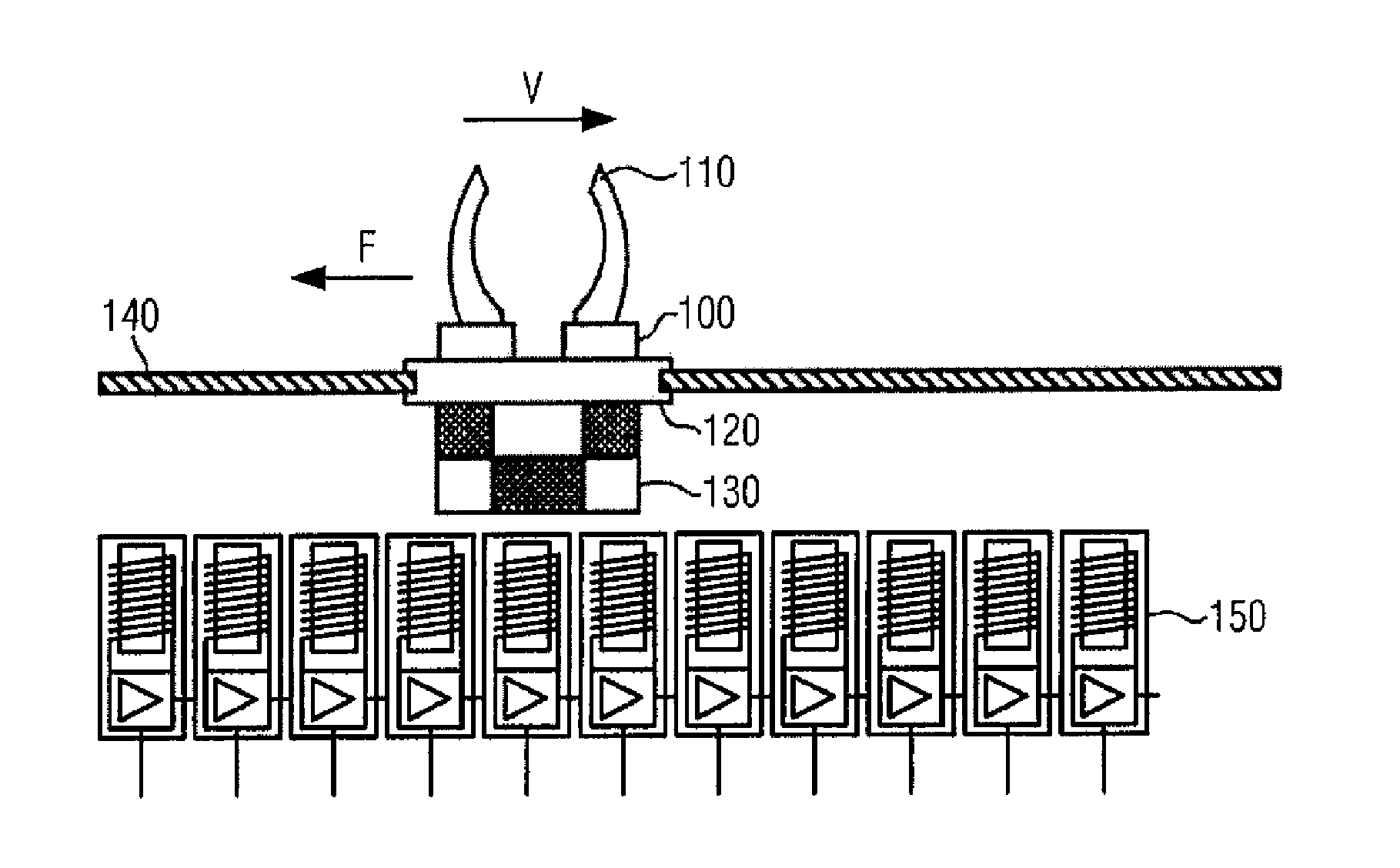
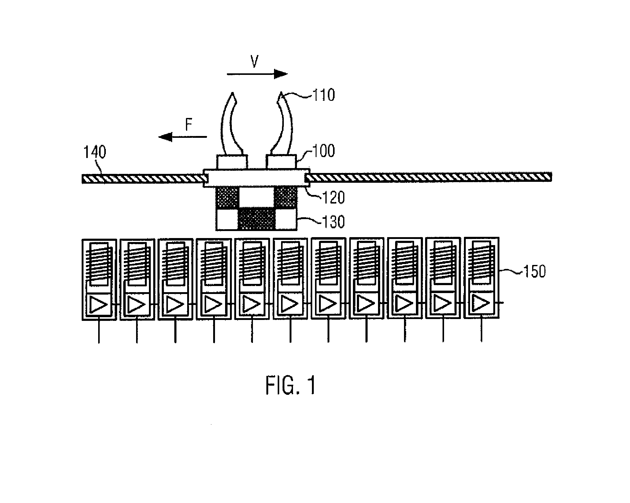
[0114]FIG. 1 exemplarily shows a conveyor element 100. The present disclosure is, however, not limited to the here shown special embodiment of the conveyor element, but is applicable to any kind of conveyor elements as long as they can be guided along a conveyor track in an individually controllable manner, especially when this is done by means of magnetic interaction with the conveyor track. The here shown conveyor element 100 can be guided along the conveyor track by means of a guide rail 140. According to this special embodiment, the conveyor element is supported on the guide rail 140 by a plain bearing 120. The figure additionally shows a gripper element 110 by means of which the conveyor element is able to pick up the containers.

[0115]The here shown passive conveyor element is driven by magnetic interaction between the reaction element 130 of the conveyor element and a large number of electric coils 150 along the conveyor track. The electric coils 150 can be controlled individu...


PUM

PropertyMeasurementUnit
Thicknessaaaaaaaaaa
Speedaaaaaaaaaa
Abrasiveaaaaaaaaaa

Abstract

A conveyor arrangement for conveying containers in a container treatment system, including a conveyor track, at least one conveyor element movably arranged on the conveyor track and used for conveying one or a plurality of containers, a conveyor element servicing device connected to the conveyor track, and an open-loop and/or closed-loop control unit, where the conveyor track and the conveyor element are configured such that the conveyor element can be guided along the conveyor track in an individually controllable manner by means of the open-loop and/or closed-loop control unit, and where the open-loop and/or closed-loop control unit is configured to supply the conveyor element to the servicing device depending on at least one state parameter of the conveyor element.

Description

CROSS-REFERENCE TO RELATED APPLICATION[0001]The present application is the United States national phase of International Patent Application No. PCT / EP2014 / 067295, filed Aug. 13, 2014, which application claims to German Application No. 10 2013 218 394.1, filed Sep. 13, 2013. The priority application is hereby incorporated by reference.FIELD OF THE DISCLOSURE[0002]The present disclosure relates to an apparatus and a method for servicing individually controllable conveyor elements for conveying containers, in particular bottles or cans, in a system for treating the containers.BACKGROUND[0003]In container treatment systems, containers, such as bottles, cans etc., are treated in one or a plurality of successive processing steps. In so doing, the processing steps or working steps are generally carried out in separate treatment units, which may e.g. be combined as modules of a joint system concept. In order to reduce costs for the acquisition and the operation of the system, interfaces for...

Claims


Application Information

Patent Timeline
IPC IPC(8): B65G35/00B65G45/02B65G45/10B65G43/00
CPCB65G35/00B65G45/10B65G45/02B65G43/00B65G37/02B65G54/02B65G35/06
Inventor SENN, KONRADWALTER, RALF
Owner KRONES AG
Why Eureka
Try Eureka