Auto-induction stepping temporary storage object table and temporary storage method

An automatic sensing and step-by-step technology, applied in the direction of conveyor objects, electrical components, printed circuits, etc., can solve the problems of increasing production costs and operating costs, delaying normal production, and reducing production efficiency, so as to reduce production costs and operating costs. cost, avoiding low production efficiency, and high production efficiency

Active Publication Date: 2018-12-21
QUZHOU CHUANTE ELECTRONICS TECH CO LTD
View PDF12 Cites 8 Cited by
  • Summary
  • Abstract
  • Description
  • Claims
  • Application Information

AI Technical Summary

Problems solved by technology

[0003] In the production process of existing printed circuit boards, the surface of the raw material substrate needs to be coated with glue. The current glue coating method uses a glue coating platform and a feeding device installed on the side of the glue coating platform. There are gluing components for gluing, and the feeding device is used to control the continuous feeding of the circuit board substrate, and push the substrate to the gluing platform for gluing, because the gluing components on the existing gluing platform are prone to Failure, or in the process of gluing, due to the gluing of substrates of different specifications, the gluing platform needs to be repaired and replaced. In this process, the overall production line needs to be shut down, which on the one hand causes production efficiency. Reduce and delay normal production, on the other hand, increase the production cost and operating cost, resulting in the loss of the enterprise

Method used


Image

  • Auto-induction stepping temporary storage object table and temporary storage method
  • Auto-induction stepping temporary storage object table and temporary storage method
  • Auto-induction stepping temporary storage object table and temporary storage method

Examples


Embodiment Construction

[0035] The following will clearly and completely describe the technical solutions in the embodiments of the present invention with reference to the accompanying drawings in the embodiments of the present invention. Obviously, the described embodiments are only some, not all, embodiments of the present invention. Based on the embodiments of the present invention, all other embodiments obtained by persons of ordinary skill in the art without creative efforts fall within the protection scope of the present invention.

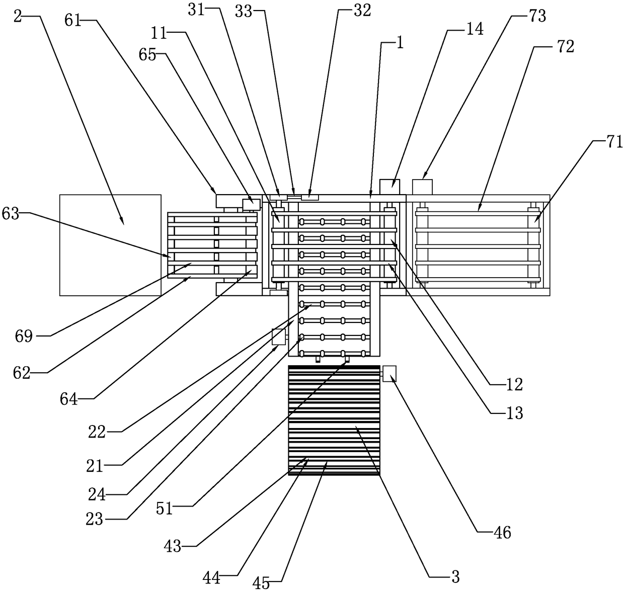
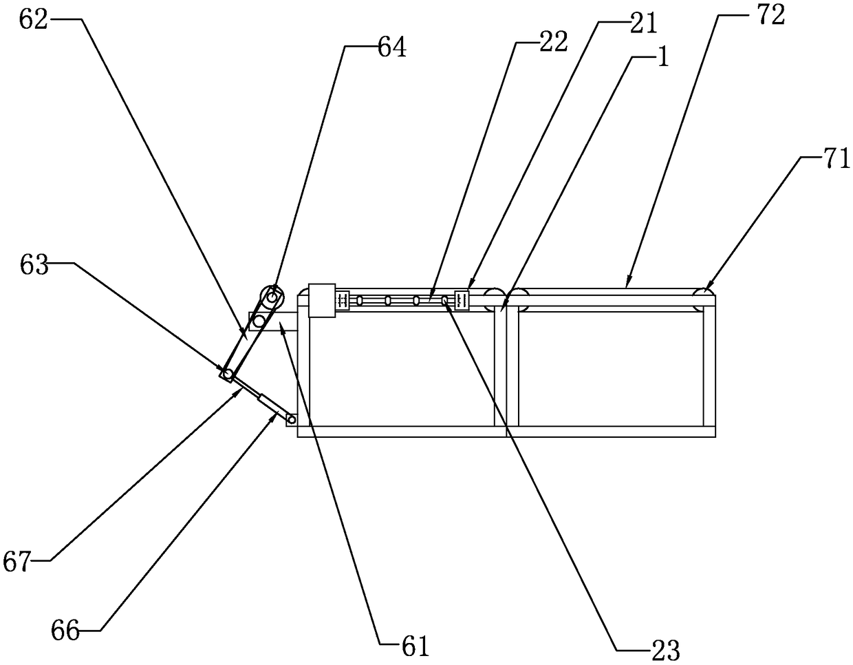
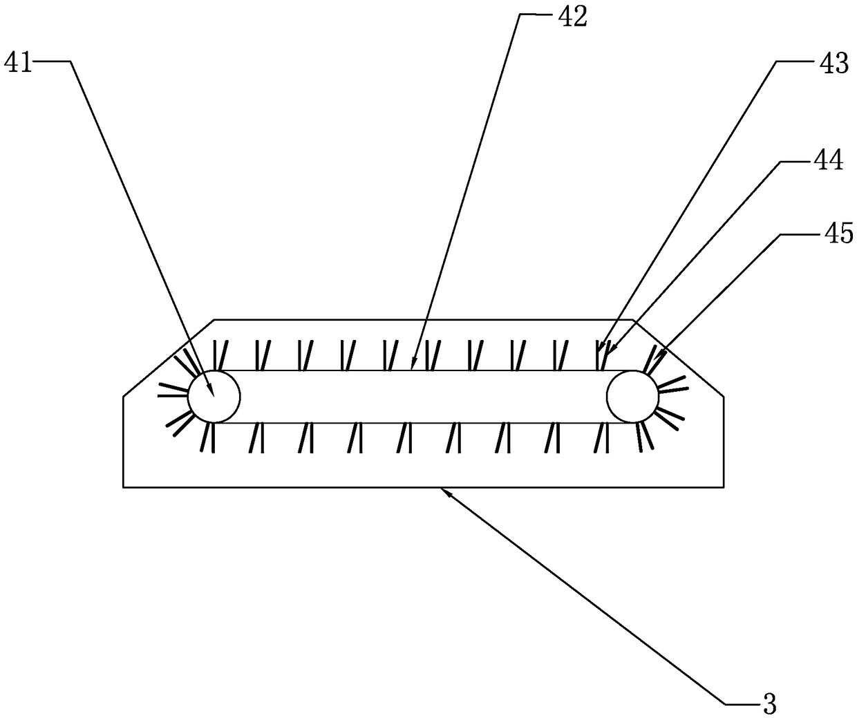
[0036] Such as Figure 1-Figure 3 As shown, the present invention discloses an automatic induction step-by-step temporary storage stage, which includes a gluing platform 2 for gluing substrates and a feeding frame 1 arranged on one side of the gluing platform 2. In a specific embodiment of the present invention, one side of the feeding frame 1 is provided with a stage 3 for temporarily storing the substrate, and the feeding frame 1 is respectively provided with a p...


PUM


Abstract

The invention relates to an auto-induction stepping temporary storage object table and a temporary storage method. The auto-induction stepping temporary storage object table comprises a coating platform used for coating a substrate and a feeding rack arranged on one side of the coating platform. An object table body used for temporarily storing the substrate is arranged on one side of the feedingrack, and the feeding rack is provided with a conveying assembly used for conveying the substrate to the coating platform and a temporary storage feeding assembly used for conveying the substrate to the object table body in the maintaining and replacing process of the coating platform. The feeding rack is arranged on one side of the coating platform, and the object table body is arranged on one side of the feeding rack; when the coating platform is in a normal working state, the substrate is conveyed to the coating platform by the feeding assembly arranged on the feeding rack to be subjected to coating action; in the maintaining and replacing process of the coating platform, the temporary storage feeding assembly arranged on the feeding rack is switched to convey the substrate on the feeding rack to the object table body, and therefore the problem that production is suspended in a whole production line due to the maintaining and replacing of the coating platform is solved.

Description

technical field [0001] The invention relates to the technical field of circuit board production, in particular to an automatic induction step-by-step temporary storage carrier and a temporary storage method thereof. Background technique [0002] Printed circuit board {PCB circuit board}, also known as printed circuit board, is the provider of electrical connections for electronic components. Its development has a history of more than 100 years; its design is mainly layout design; the main advantage of using circuit boards is that it greatly reduces wiring and assembly errors, and improves automation and production labor rates. Before the appearance of printed circuit boards, the interconnection between electronic components relied on the direct connection of wires to form a complete circuit. In contemporary times, circuit panels only exist as effective experimental tools, and printed circuit boards have become an absolute dominant position in the electronics industry. In t...

Claims


Application Information

Patent Timeline
Patent Type & Authority Applications(China)
IPC IPC(8): B65G47/69H05K3/00
CPCH05K3/0091B65G47/69Y02P70/50
Inventor 兰胜有
Owner QUZHOU CHUANTE ELECTRONICS TECH CO LTD
Why Eureka
Try Eureka