Signal processing device

a signal processing and signal technology, applied in the field of signal processing devices, can solve the problems of large hardware load, increased hardware load and cost, and large hardware load, and achieve the effects of reducing cost, simple hardware configuration, and efficient removal of background signals

Inactive Publication Date: 2016-07-07
PANASONIC INTELLECTUAL PROPERTY MANAGEMENT CO LTD
View PDF1 Cites 10 Cited by
  • Summary
  • Abstract
  • Description
  • Claims
  • Application Information

AI Technical Summary

Benefits of technology

[0016]The invention is achieved in view of the above circumstances, and an object thereof is to provide a signal processing device capable of efficiently removing the background signal to obtain the desired signal with a comparatively simple hardware configuration achieved by a lower cost.
[0030]The signal processing device of the invention includes the signal processor operating as the frequency-domain adaptive filter configured to remove the background signal from the sensor signal based on the Discrete Cosine Transform processing. Accordingly, it is possible to efficiently remove the background signal to obtain the desired signal with a simple hardware configuration achieved by a lower cost.

Problems solved by technology

Further, because of requiring performing complex number calculation, this adaptive filter requires a comparatively large-scale hardware.
Furthermore, the subsequent adaptive-processing and filtering processing requires performing complex number calculation, which causes larger load on the hardware.
Therefore, if the frequency-domain adaptive filter using FFT is applied to a signal processing device that processes a sensor signal, problems are raised that the load on the hardware and the cost thereof would increase.
These problems of increasing load on the hardware and increasing cost has been one obstacle for the application of the filter to a commercial sensor device which typically requires a lowered cost.

Method used


Image

  • Signal processing device
  • Signal processing device
  • Signal processing device

Examples


Embodiment Construction

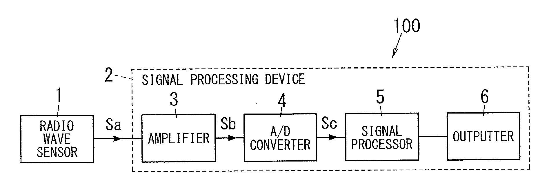
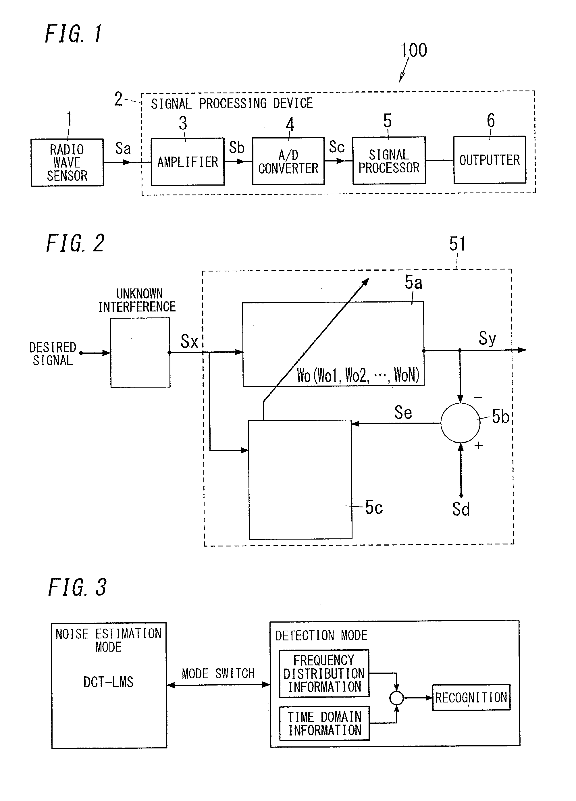
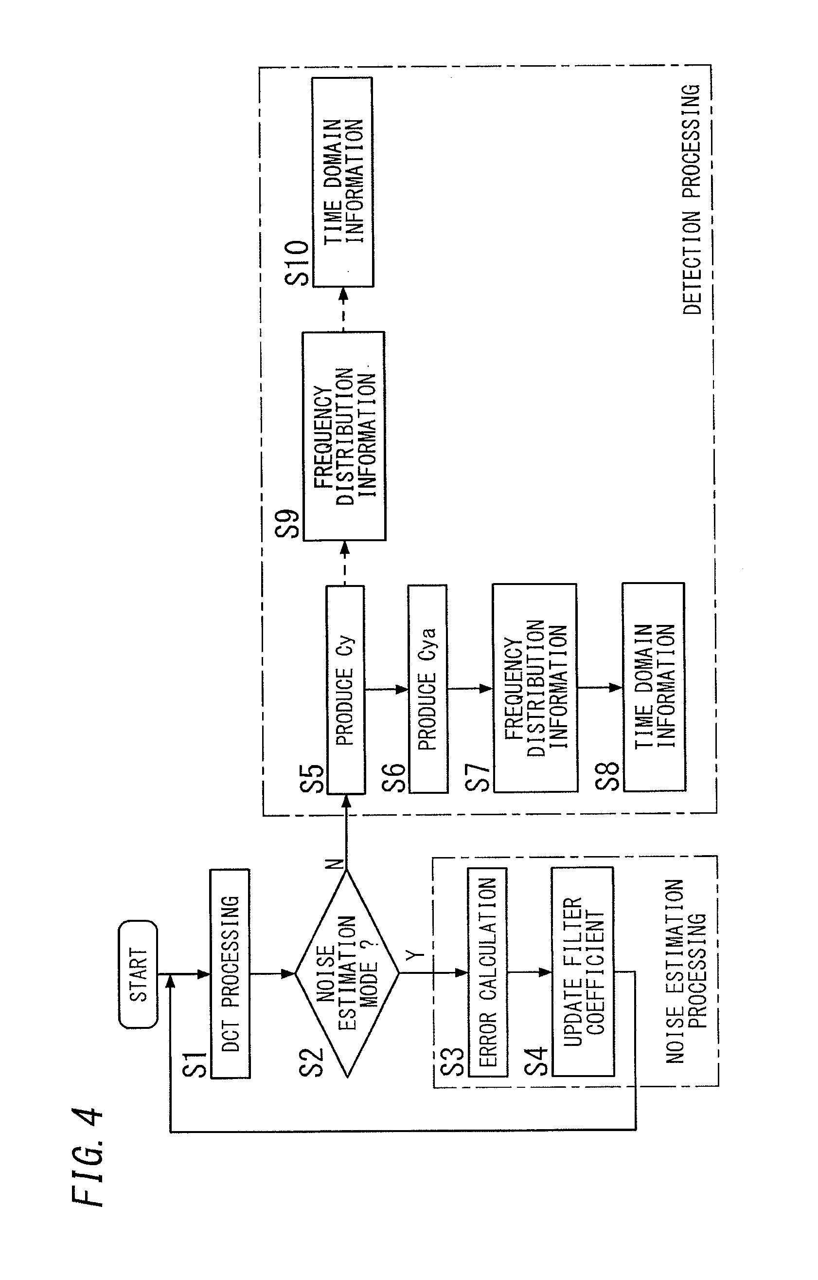
[0043]Hereafter, a signal processing device 2 in the present embodiment will be described with reference to FIGS. 1 to 11.

[0044]The signal processing device 2 is configured to process a sensor signal Sa output from a radio wave sensor 1. The radio wave sensor 1 is configured to transmit a radio wave in a detection area, to receive a radio wave reflected by an object in the detection area, and to output a sensor signal Sa which reflects the movement of the object. FIG. 1 is a block diagram of a sensor device 100 including the radio wave sensor 1 and the signal processing device 2.

[0045]The radio wave sensor 1 of the embodiment is a Doppler sensor configured to transmit a radio wave having a predetermined frequency to a detection area, to receive the radio wave reflected by an object moving in the detection area, and to output a sensor signal having a Doppler frequency which is equivalent to a difference between the transmitted and received radio waves. The sensor signal Sa output fro...


PUM


Abstract

A signal processing device (2) includes an amplifier (3), an A / D converter (4) and a signal processor (5). The amplifier (3) amplifies a sensor signal that is supplied from a radio wave sensor (1) and depends on a motion of an object. The A / D converter (4) converts the sensor signal amplified by the amplifier (3) into a digital sensor signal. The signal processor (5) converts the sensor signal output from the A / D converter (4) into a frequency-domain sensor signal by Discrete Cosine Transform processing, estimates a background signal contained in the frequency-domain sensor signal, based on an error signal obtained from the sensor signal and a reference signal which is white noise, and determines a filter coefficient according to the estimated background signal, thereby operating as an adaptive filter for removing the background signal from the sensor signal in the frequency domain.

Description

TECHNICAL FIELD[0001]The invention relates to a signal processing device configured to process sensor signals from a sensor that receives a wireless signal reflected by an object.BACKGROUND ART[0002]There has been proposed a lighting system having a configuration shown in FIG. 12 (for example, see JP2011-47779A; hereinafter referred to as “Document 1”). This lighting system includes: an object detection device 101 provided with a sensor 110 that detects the presence or absence of a detection target object in a detection area and outputs a sensor signal; and a lighting apparatus 102. The object detection device 101 controls a lighting state of the lighting apparatus 102.[0003]The sensor 110 is a millimeter-wave sensor that transmits a millimeter wave to the detection area, receives a millimeter wave reflected by the detection target object moving in the detection area, and outputs a sensor signal having a Doppler frequency which is equivalent to a frequency difference between the tra...

Claims


Application Information

Patent Timeline
Patent Type & Authority Applications(United States)
IPC IPC(8): G01S7/02G01S13/56
CPCG01S13/56G01S7/023G01S7/354G01S7/356
Inventor SUGINO, SATOSHI
Owner PANASONIC INTELLECTUAL PROPERTY MANAGEMENT CO LTD
Why Eureka
Try Eureka