Method and apparatus for focal spot position tracking

a technology of focal spot and position tracking, applied in the field of focal spot position tracking, can solve the problems of incongruity between acquired data, inaccuracy and/or artifacts in reconstructed images, and significant errors, and achieve the effect of high accuracy tracking

Inactive Publication Date: 2016-07-14
ARINETA
View PDF19 Cites 17 Cited by
  • Summary
  • Abstract
  • Description
  • Claims
  • Application Information

AI Technical Summary

Benefits of technology

[0012]According to an aspect of some embodiments of the present invention there is provided a dedicated tracking system for tracking focal spot movement of a radiation source during scanning. In some exemplary embodiments, the dedicated tracking system is suitab...

Problems solved by technology

Consequently, any mechanical misalignments and/or displacement of the various tomography components during data acquisition can potentially cause inaccuracies and/or artifacts in the reconstructed images.
One known cause of misalignment is related to movement of the radiation source during scanning.
This shift results in inconsistency within the acquired data.
For CT sc...

Method used


Image

  • Method and apparatus for focal spot position tracking
  • Method and apparatus for focal spot position tracking
  • Method and apparatus for focal spot position tracking

Examples


Embodiment Construction

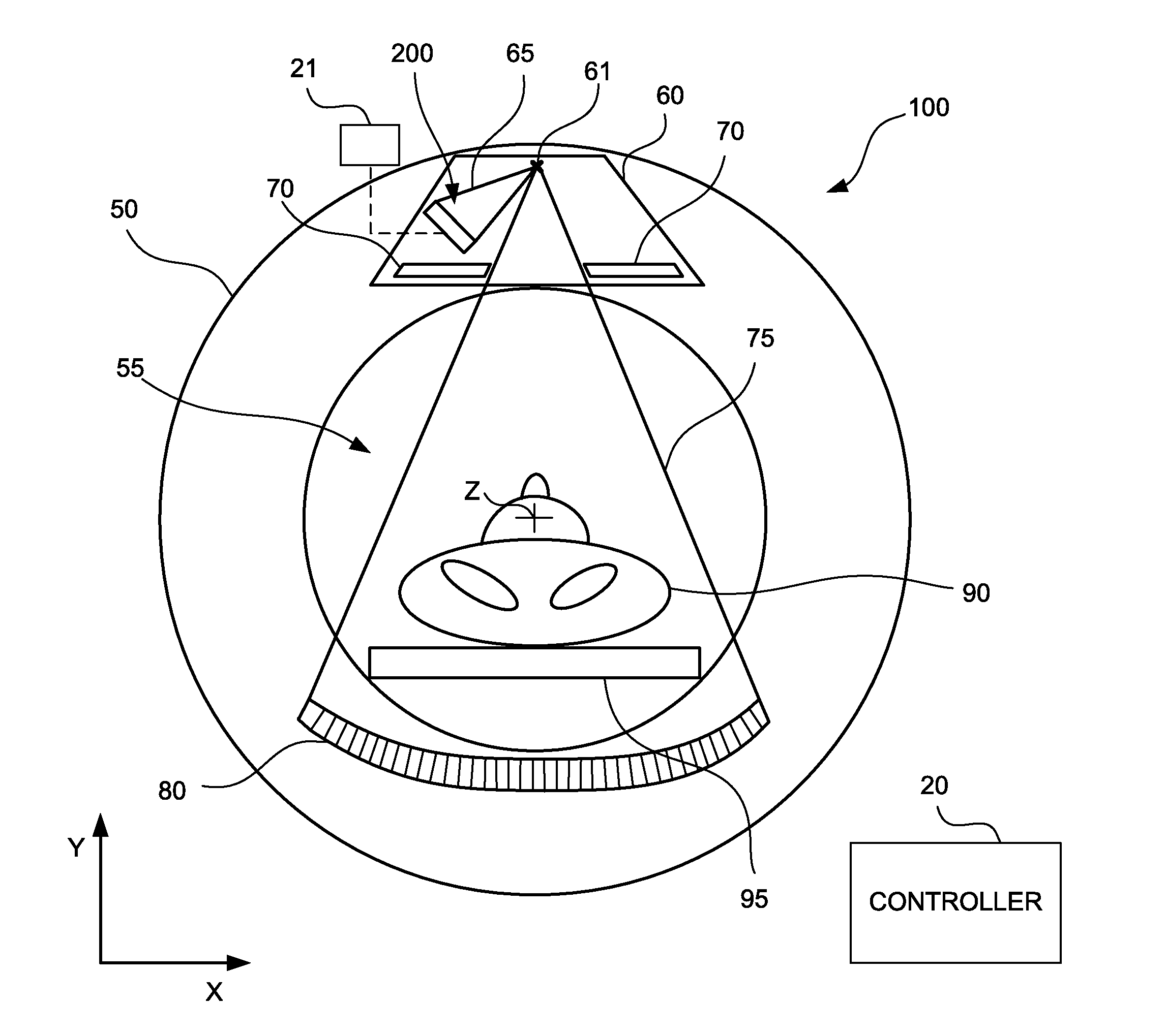
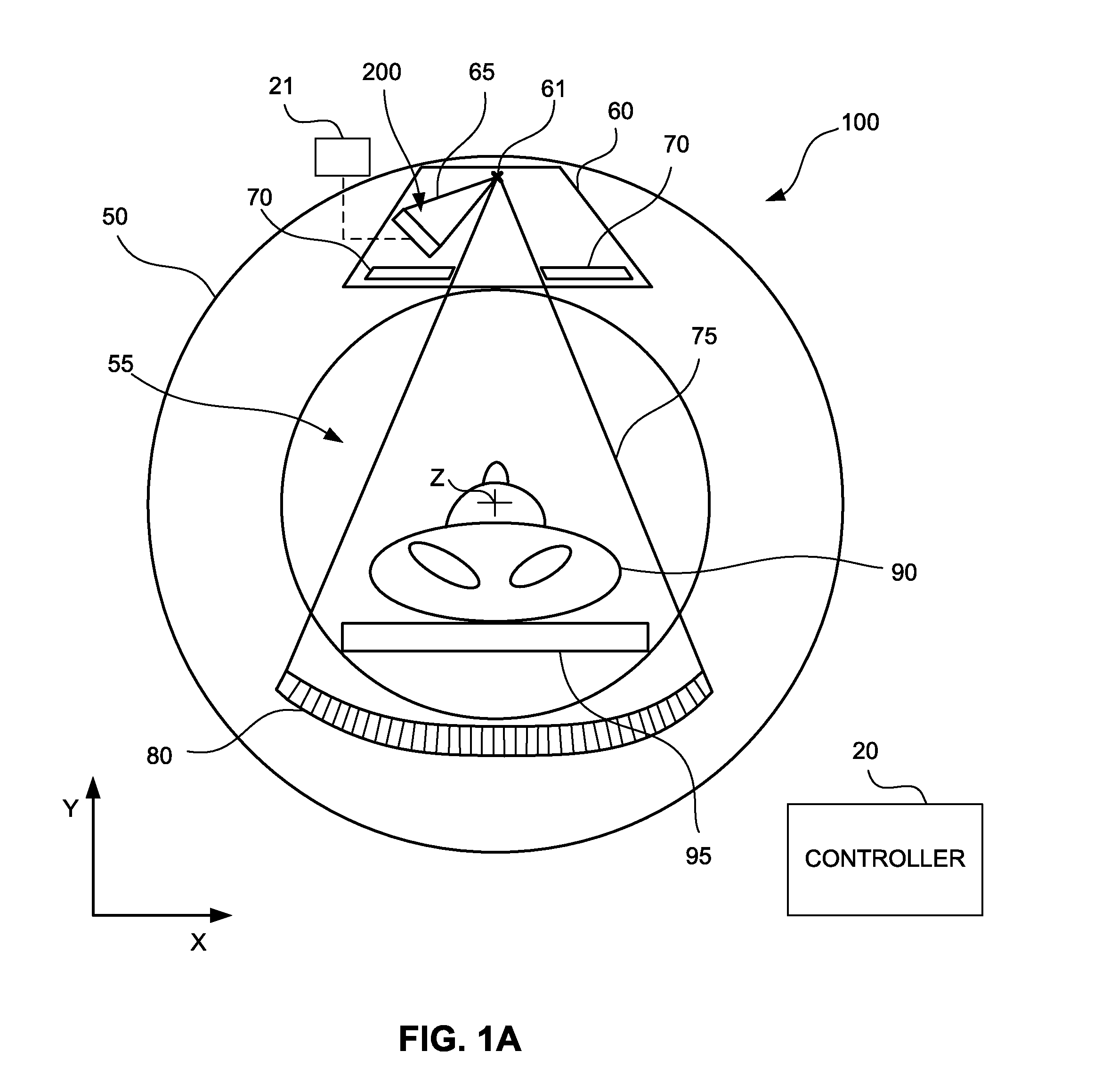
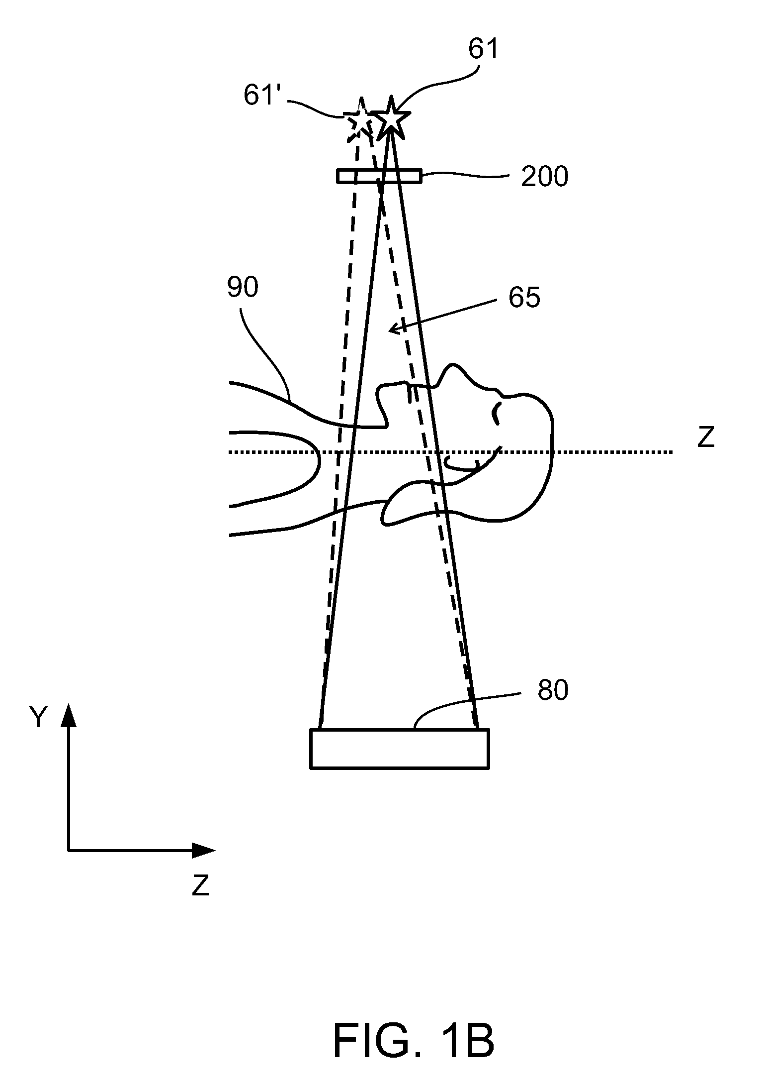
[0053]The present invention, in some embodiments thereof, relates to focal spot position tracking of a radiation source and, more particularly, but not exclusively, to focal spot position tracking for radiation scanners, such as CT scanners and the like.

[0054]U.S. Pat. No. 7,284,905 referenced hereinabove describes focal spot tracking by projection of the focal spot image through a slit or a pin hole onto an X-ray sensitive sensor and detection of motion of the projected focal spot image on the sensor. The slit cannot typically be placed very close to the focal spot because of constrains of the radiation source structure which further distances he X-ray sensitive sensor from the focal spot. On the other hand, to get high sensitivity to focal spot motion it is desired to have high magnification, achievable by placing the sensor as far as practical from the slit. Thus, prior art solutions are feasible only if sufficient distance can be provided between the elements of the tracking sys...


PUM


Abstract

A tracking system for tracking focal spot position of an x-ray source includes a detector array including a plurality of detecting elements sensitive to x-ray radiation and a grid overlaid on a detecting surface of the detector array. The grid is formed from an array of vanes and has a density greater than a density of the detector array.

Description

FIELD AND BACKGROUND OF THE INVENTION[0001]The present invention, in some embodiments thereof, relates to focal spot position tracking of a radiation source and, more particularly, but not exclusively, to focal spot position tracking for radiation scanners, such as computed tomography (CT) scanners and the like.[0002]CT scanners have found wide application in many areas including quality inspection, security and medical imaging. CT scanners typically include a radiation source and a detector array positioned on diametrically opposing sides of a rotating gantry. During a scan of an object, the object is placed in an examination region of the scanner and the gantry rotates about the object while radiation is emitted from a focal spot of the radiation source. Many conventional CT scanners use a collimator to shape the X-ray radiation beam emitted from the focal spot. Typically, the collimator directs the X-ray radiation beam in a direction generally perpendicular to an axis of rotation...

Claims


Application Information

Patent Timeline
IPC IPC(8): A61B6/00A61B6/03
CPCA61B6/547A61B6/4291A61B6/03A61B6/032A61B6/4021A61B6/5258
Inventor RUIMI, DAVIDVOLOKH, LANAKUKSIN, EVGENIY
Owner ARINETA
Why Eureka
Try Eureka