Radar sensing of vehicle occupancy

a technology of vehicle occupancy and radar sensing, which is applied in the direction of pedestrian/occupant safety arrangement, applications, instruments, etc., can solve the problems of high integration cost, insufficient in order to get a reliable indication, and the inability to establish radar-based in-vehicle systems on the mark

Active Publication Date: 2016-07-14
IEE INT ELECTRONICS & ENG SA
View PDF3 Cites 38 Cited by
  • Summary
  • Abstract
  • Description
  • Claims
  • Application Information

AI Technical Summary

Benefits of technology

[0043]In embodiments, rather than employing conventional CW radar for radar motion sensing, a frequency modulated CW (FMCW) radar is used, in order to obtain range information for the motion signal, whether it is in the interior or the exterior of the car cabin. A DC offset removal operation on every single frequency measurement allows static objects to be disregarded and for the system to focus on moving objects such as humans.

Problems solved by technology

State of the art systems for occupant classification and detection are foil based systems which are integrated in every single seat (involving high integration costs).
Radar based in-vehicle systems are not established on the market due to high costs.
This is not sufficient in order to get a reliable indication of the occupancy status or of whether the human is inside or outside the car.

Method used


Image

  • Radar sensing of vehicle occupancy
  • Radar sensing of vehicle occupancy
  • Radar sensing of vehicle occupancy

Examples


Embodiment Construction

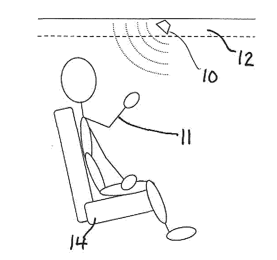
[0058]Radar sensing within a complex environment like the interior of a car cabin is very challenging and the algorithm differs much from those for exterior radar sensing.

[0059]The advantage of radar systems is that in contrast to passive camera systems the radar system operates also in the night as it illuminates actively the scene. Active camera systems need an illumination in the light spectrum which can be visible for the human eye (compare to the glooming of infrared cameras). Radar systems work in the microwave range which is completely invisible for the human eye. In addition it penetrates into materials and can transmit through. So the integration behind plastic covers and textiles as well is possible while camera based systems need an opening to look through.

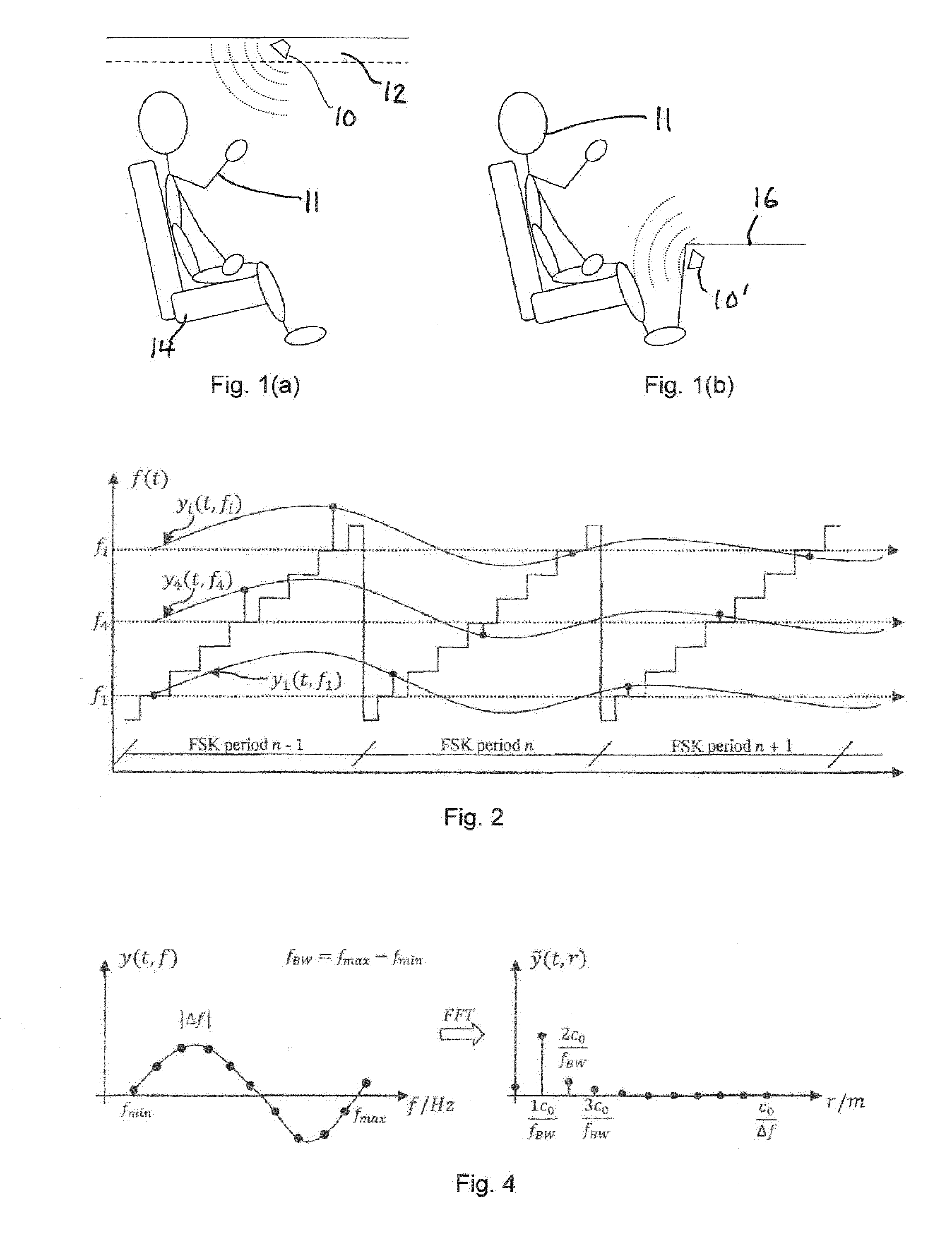
[0060]In one embodiment, the radar detection system has nearly fixed and constant antenna lobes over the whole frequency range from 24.00 GHz up to 24.25 GHz; however, the invention is not restricted to this frequency r...


PUM


Abstract

A method for sensing occupancy status within an automotive vehicle uses a radar sensor system, the radar sensor system comprising an antenna system, at least one sensor (10) and processing circuitry (18). The method comprises illuminating, using the antenna system, at least one occupiable position within the vehicle with continuous wave (CW signals), the CW signals being frequency modulated in time. At least one sensor signal (a) reflected as a result of the CW signals, is received using at least one sensor (10) the at least one sensor (10) defining a plurality of receive channels (1 . . . i), each channel having a different frequency (f1 . . . fi). Processing circuitry (18) is operable for applying, for each receive channel (1 . . . i), DC offset removal to the corresponding sensor signal (a) to generate a modified signal (b); and generating, based on the modified signals (b) one or more occupancy status signals (34, 38), the occupancy status signal indicating a property related to said at least one occupiable position. A system for carrying out the method is also disclosed. The techniques provide for in-vehicle occupant detection and classification (airbag suppression), for passenger presence detection and passenger's vital sign monitoring and for seat-belt reminder functionality (SBR). The radar system may consist of one or two (or four) outputs (I/Q) per channel. The received signal may be mixed down with a single channel demodulator or an I/Q demodulator into the baseband. An advanced signal processing including an auto calibration routine and clutter removal may be used to detect occupants and their vital sign (breathing and heart beat) and to determine their distance to the radar system.

Description

TECHNICAL FIELD[0001]The present invention generally relates to the technical field of sensing objects internal to a vehicle, and more specifically to FMCW radar sensing for detecting occupants in a vehicle.BACKGROUND ART[0002]State of the art systems for occupant classification and detection are foil based systems which are integrated in every single seat (involving high integration costs). It is also known to provide for contactless sensing (e.g. of humans) within a vehicle, e.g. for occupancy detection (OD), occupancy classification (OC) or seat-belt reminder (SBR) functionality. Radar based in-vehicle systems are not established on the market due to high costs. In general, each single seat needs a separate radar sensor.[0003]Radar technology offers some advantages in comparison to other occupancy detection and classification methods. It is a contactless and invisible measurement system which can easily be integrated behind plastic covers and textiles. Radar systems can measure t...

Claims


Application Information

Patent Timeline
Patent Type & Authority Applications(United States)
IPC IPC(8): B60R21/015A61B5/00G01S7/35A61B5/05G01S13/56G01S13/34
CPCB60R21/01534B60R21/0153G01S13/56A61B5/6893G01S7/354A61B5/05G01S13/34B60R21/015G01S7/415G01S13/04G01S13/88
Inventor DIEWALD, ANDREAS
Owner IEE INT ELECTRONICS & ENG SA
Why Eureka
Try Eureka