Hydrostatic Fluid Containment System

a technology of hydrostatic fluid and containment system, which is applied in the direction of hydroelectric engineering, dykes, marine site engineering, etc., can solve the problems of increased insurance premiums, decreased property values, and loss of income, and achieve the effect of optimal operation and minimum maintenance requirements

Active Publication Date: 2016-07-14
ROY SCOTT
View PDF4 Cites 18 Cited by
  • Summary
  • Abstract
  • Description
  • Claims
  • Application Information

AI Technical Summary

Benefits of technology

[0023]In a further aspect of the invention the rotating wall equilibrium is positioned on said pivot seal with a guide bracket which compresses said seal into a counter lever support frame. Vertical partitions in said wall create a bending moment shorter than that of a horizontal continuous beam reducing the deflection forces acting on said wall by the contained hydrostatic loads.

Problems solved by technology

Loss of income due to business closure, increased insurance premiums and decreased property values may be experienced after significant fluid damage such as tidal surges, stormwater runoff, burst water pipes or industrial spills.
In events such as these members of the community are often left unprepared and under resourced.
Repair and replacement cost to property and infrastructure can be significant if effected by fluid damage during floods or industrial accidents.
The time taken to clean up fluid damage may be increased due to access restrictions of property, equipment and machinery.
Permanent conventional flood barriers can restrict the movement of vehicles and pedestrians while temporary barriers such as sand bags and demountable walls may be in limited supply or difficult to access during emergencies.
The barriers float up and above ground when enough water is received however this action occurs before floodwater is actually flowing across the ground surface thereby restricting vehicles and pedestrian traffic where they would normally be trying to get to a safe location before the actual flood water became a real risk.
Fluids raising a wall before surface fluid flows are encountered create an unnecessary restriction above ground level.
Fluid entry points below ground level which float the barrier before surface flows are a threat.
Even with risers inside of entry pits, the barriers still float before surfaces flows are actually at ground level which restricts vehicle and pedestrian traffic.
Fluid entry points below ground and connected directly to stormwater drainage networks will raise prematurely as the piping pressurizes under normal design flow.
Piping that transfers fluid from entry pits to interception channels interfere with existing underground services.
Guide frames for barrier seals interfere with barrier removal and require multiple calibrations points.
Support blocks and pipe risers in entry pits restrict the ability to install filtration screens.
Barriers that retract horizontally into the ground can be damaged by vehicle traffic passing above.

Method used


Image

  • Hydrostatic Fluid Containment System
  • Hydrostatic Fluid Containment System
  • Hydrostatic Fluid Containment System

Examples


Embodiment Construction

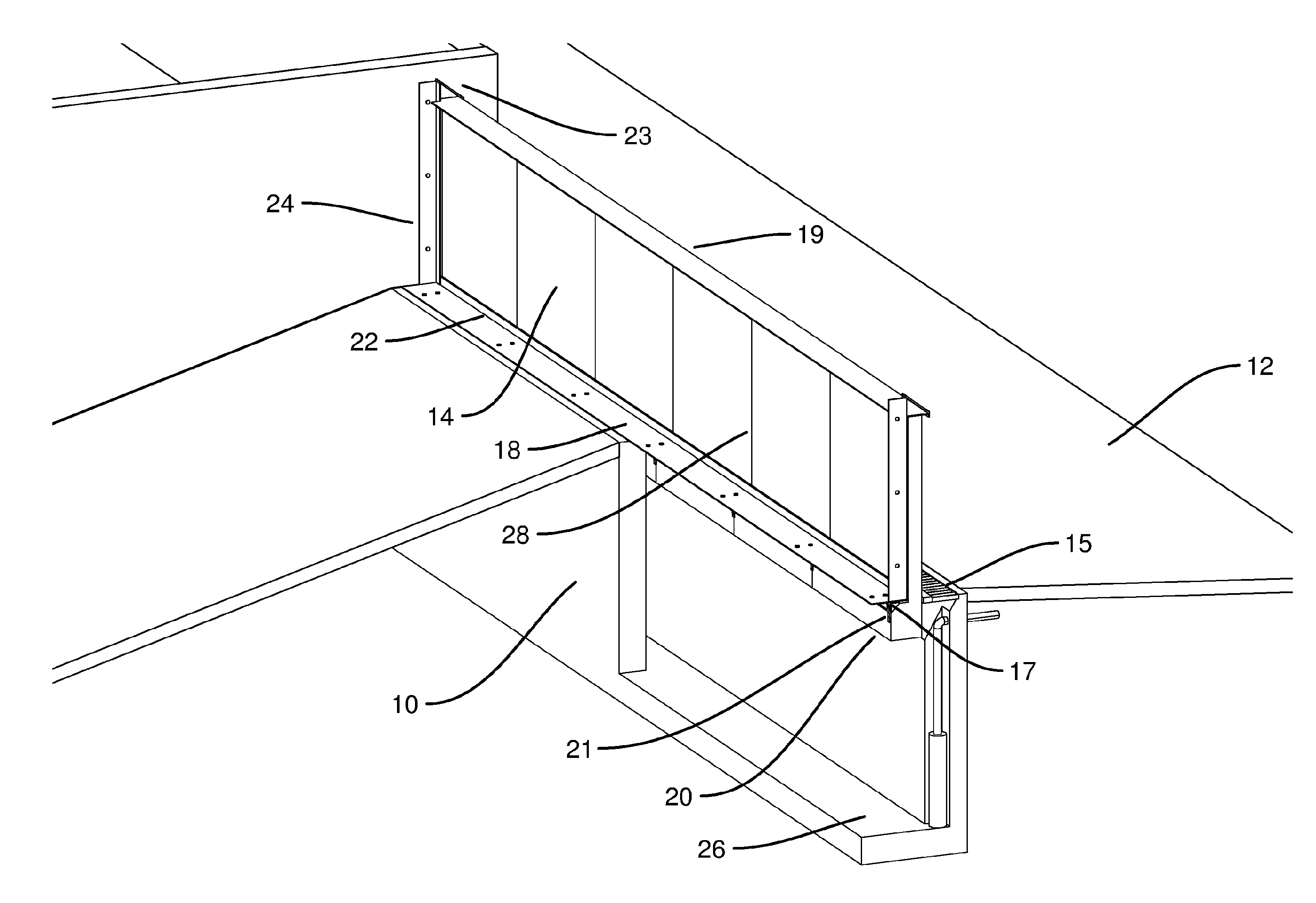
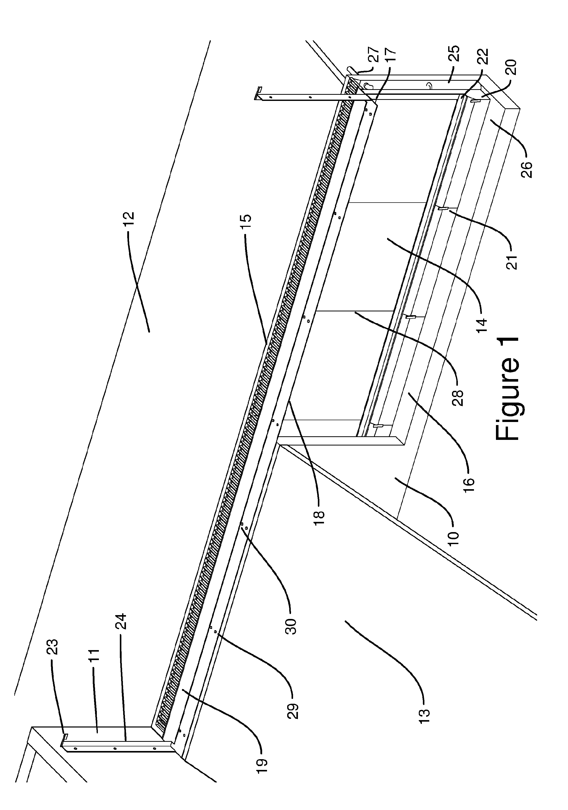
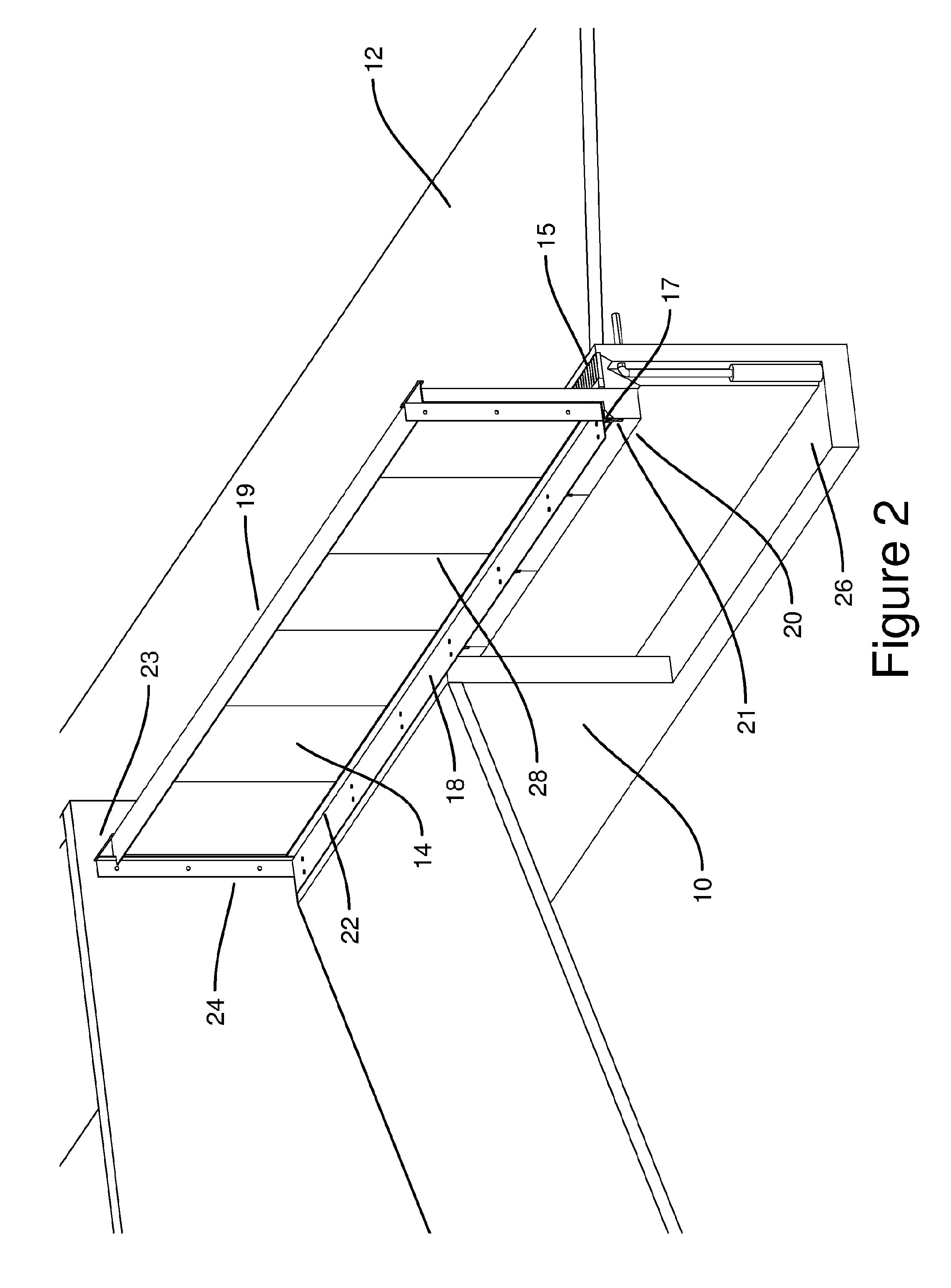
[0054]It is preferable that the hydrostatic fluid containment system apparatus be constructed from 150 mm reinforced precast concrete fitted with lifting lugs to achieve uniform horizontal and vertical faces to enable the internal and external fabricated components of the device to be fitted to smooth surfaces of the chamber 16 and to allow for lifting, transportation and installation. Alternatively corrosion resistant steel treated metal, plastic or composite material could deliver a similar smooth surface for component precision. Chamber 16 is preferably located between smooth boundary walls 11 to facilitate watertight joins between vertical guide wall frames 24 which should be constructed from 5 mm thick stainless steel angle extrusions to prevent stormwater passing between boundary walls 11 and buoyant wall 14 from reaching dry zone 13.

[0055]It is preferable that sealing rubber 22 be constructed from 25 mm diameter half round hollow rubber tube with a 25 mm flat continuous tag a...


PUM


Abstract

A hydrostatic fluid containment system, or flood barrier, that is positioned underground in its open state consisting of a buoyant wall which floats up and above ground level when submerged in a fluid, creating a seal from both buoyant vertical and hydrostatic horizontal forces on the containment wall imposed by the contained fluid. The system will not open prematurely and restrict access of vehicles or pedestrians until containment is necessary. The system comprises a pivot seal which seals the barrier on the upstream side, as well as another sealing element that is positioned between the pivot seal and the buoyant wall. The pivot helps to tilt the barrier towards the upstream direction.

Description

BACKGROUND OF THE INVENTION[0001]Loss of income due to business closure, increased insurance premiums and decreased property values may be experienced after significant fluid damage such as tidal surges, stormwater runoff, burst water pipes or industrial spills. In events such as these members of the community are often left unprepared and under resourced.[0002]Repair and replacement cost to property and infrastructure can be significant if effected by fluid damage during floods or industrial accidents. The time taken to clean up fluid damage may be increased due to access restrictions of property, equipment and machinery.[0003]Permanent conventional flood barriers can restrict the movement of vehicles and pedestrians while temporary barriers such as sand bags and demountable walls may be in limited supply or difficult to access during emergencies.[0004]In one example of a floating barrier a combination service and entry pit receives floodwater from a river or ground surface area. T...

Claims


Application Information

Patent Timeline
Patent Type & Authority Applications(United States)
IPC IPC(8): E02B3/10
CPCE02B3/104E02B3/102E06B9/04E06B2009/007
Inventor ROY, SCOTT
Owner ROY SCOTT
Why Eureka
Try Eureka