Method for controlling fluid interface level in gravity drainage oil recovery processes with crossflow

a technology of gravity drainage and fluid interface, applied in the direction of fluid removal, borehole/well accessories, survey, etc., can solve the problems of non-uniform permeability of heavy oil or oil sands reservoir, non-uniform depletion of areas, and non-uniform depletion of reservoirs, so as to improve the recovery of hydrocarbons from subterranean formations, the effect of reducing the pressure loss through the tubing and reducing the risk o

Active Publication Date: 2016-07-14
NOETIC TECH INC
View PDF0 Cites 23 Cited by
  • Summary
  • Abstract
  • Description
  • Claims
  • Application Information

AI Technical Summary

Benefits of technology

[0014]The present disclosure teaches methods facilitating the design or selection of means to limit liquid inflow into the producer well from high permeability areas and to control flow from areas with different permeabilities based on liquid level to match reservoir delivery rate. For example, methods in accordance with the disclosure can be used:
[0044]In addition to flowing radially from the fluid interface to the producer well, liquid may flow axially (i.e, parallel to the producer well) through the near-wellbore reservoir. For purposes of this patent specification, axial flow through the near-wellbore reservoir will be alternatively referred to as “crossflow”. The steps comprising the characterization of the gravity IPR—namely, temperature measurements, analysis boundary definition, temperature mapping, and numerical or analytical analysis—also enable accurate calculation of the axial hydraulic conductivity of the liquid inventory and, in turn, the axial flow rate.

Problems solved by technology

The permeability of a heavy oil or oil sands reservoir is non-uniform, or “heterogeneous”.
Areas with high permeability will tend to allow steam and oil to flow more easily through them; thus these areas are more likely to be depleted sooner than areas with low permeability.
Commonly used producer completion strategies provide little restriction to inflow from high permeability areas, so it is likely that reservoirs will be depleted non-uniformly over the length of the well.
This could lead to ineffective distribution of steam during the life of the well, which would reduce the overall efficiency of the process.

Method used


Image

  • Method for controlling fluid interface level in gravity drainage oil recovery processes with crossflow
  • Method for controlling fluid interface level in gravity drainage oil recovery processes with crossflow
  • Method for controlling fluid interface level in gravity drainage oil recovery processes with crossflow

Examples


Embodiment Construction

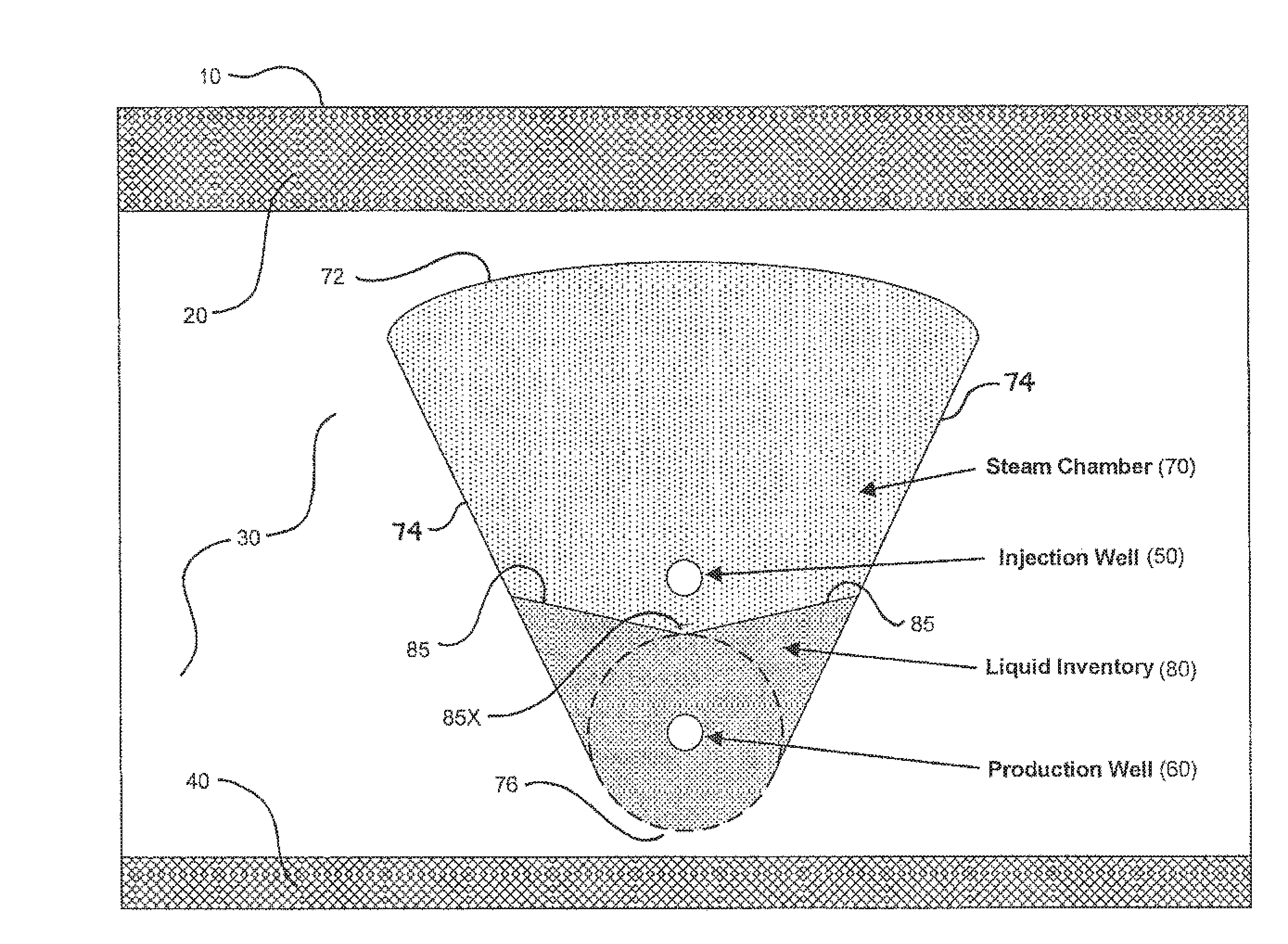
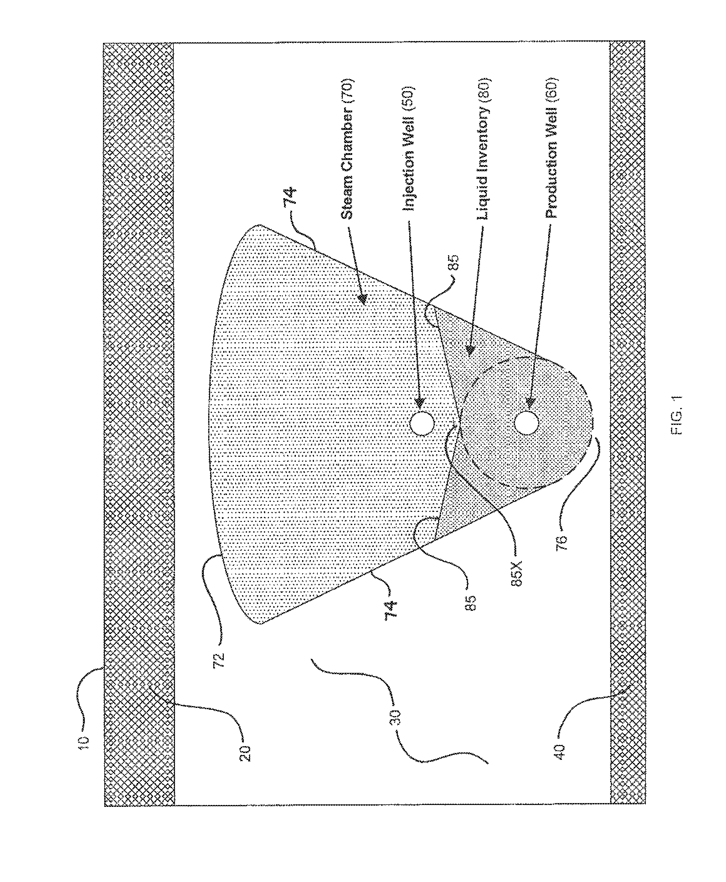
[0071]FIG. 1 schematically illustrates a horizontal well pair (i.e., injector and producer) in a typical SAGD bitumen recovery installation in a bitumen-laden subterranean oil sands formation 30 underlying an overburden layer 20 extending to the ground surface 10, and overlying an underburden formation 40, all in accordance with prior art knowledge and well within the understanding of persons of ordinary skill in the art. Steam under high pressure is introduced into injector well 50 from a connecting well leg (not shown) extending to ground surface 10. Injector 50 has a slotted or orificed liner such that steam exits injector 50 through the liner slots or orifices and permeates oil sands formation 30 to create a steam chamber 70 within formation 30. In this context, the term “steam chamber” may be understood to mean a volume within formation 30 in which steam remains present and mobile, at least for so long as steam injection into formation 30 continues. For analytical purposes, it ...


PUM


Abstract

In a method for controlling the interface level between a liquid inventory and an overlying steam chamber in a subterranean petroleum-bearing formation, an inflow relationship is developed to predict the vertical position in a gravity field of the interface between two fluids with a density contrast (most commonly a water / oil emulsion and steam), relative to a horizontal producer well. The inflow relationship is applied to producer well completions by designing the completion to raise or lower sand face pressures over the horizontal length of the well. This pressure distribution will affect liquid levels according to the inflow relationship. Axial flow relationships for the liquid inventory may be developed to facilitate estimation of liquid levels at selected locations. Axial flow relationships for the steam chamber may also be developed to estimate the effect of the injector well completion on the steam chamber pressure and, in turn, the liquid level.

Description

FIELD OF THE DISCLOSURE[0001]The present disclosure relates to methods for improving recovery of hydrocarbons from subterranean formations. More specifically, the disclosure relates to a method of controlling the fluid interface level above a horizontal producer well to effect the inflow of oil-bearing production fluids from the reservoir and to avoid breakthrough of gases into the producer well.BACKGROUND[0002]Gravity drainage processes are used for extracting highly viscous oil (“heavy oil”) from subterranean formations or bitumen from oil sand formations. For purposes of this patent specification, the general term “oil” will be used with reference to liquid petroleum substances recovered from subterranean formations, and is to be understood as including conventional crude oil, heavy oil, or bitumen, as the context may allow or require.[0003]For heavy oil or bitumen to drain from a subterranean formation by gravity, its viscosity must first be reduced. The Steam-Assisted Gravity D...

Claims


Application Information

Patent Timeline
Patent Type & Authority Applications(United States)
IPC IPC(8): E21B47/10E21B43/24
CPCE21B43/2406E21B47/10
Inventor KAISER, TRENT MICHAEL VICTORTAUBNER, SPENCER P.
Owner NOETIC TECH INC
Why Eureka
Try Eureka