Resonater

a technology of resonators and resonators, applied in the field of resonators, can solve the problems of relative high tool cost, and achieve the effects of reducing tool cost, easy and cost-effective production, and reducing tool cos

Inactive Publication Date: 2016-07-14
UMFOTEC +1
View PDF9 Cites 12 Cited by
  • Summary
  • Abstract
  • Description
  • Claims
  • Application Information

AI Technical Summary

Benefits of technology

[0010]By dispensing with the single-piece construction of the chambers and by combining the annular chambers of at least one U-shaped and one L-shaped chamber, it is possible, on the one hand, for the individual chambers to be produced more cost-effectively with lower tool costs, while on the other hand, because of their modular structure, they can be more easily and cost-effectively adapted to different installation spaces and different damping conditions. In particular, the width parallel to the resonator longitudinal axis of the first and third annular chambers with an L-shaped wall can be easily modified. Another simple and cost-effective variation of the damping characteristics can be achieved via the number and geometry of the wall holes in the inner pipe which are assigned to the annular chambers. In principle, the intended damping results from the volumes of the annular chambers and from the size of the wall holes in the inner pipe that connect the inner space of the inner pipe with the volume chambers. To achieve damping across a broad spectrum, it is advantageous to design the annular chambers with differing volumes and corresponding wall holes in the inner pipe and to coordinate these with one another. Appropriate adaptation of the wall holes to the volumes of the volume chambers results in the known action mechanisms of the Helmholtz type and / or in the manner of λ / 4 resonators, which serve to lower noise for the entire arrangement.
[0011]The chosen construction of the annular chambers and of the inner pipe achieves especially high production flexibility, since the manufacturing methods are not bound to any particular tools or molds and they can be rapidly and simply adapted. Manufacturing methods not bound to any particular tools or molds include processes such as welding, lasering, cutting, pressurization of semi-finished pipes, blow molding techniques, deep drawing, etc. For instance, the first and third annular chambers can be formed as a single piece, e.g. by pressurization, then in a subsequent work step, they can be separated into the first and third annular chamber by cutting or another separation process.
[0012]According to one embodiment of the invention, a third annular chamber that has an L-shaped circumferential wall coaxial to the resonator longitudinal axis is provided, which L-shaped circumferential wall, at its end facing away from the first annular chamber, transitions into a cylindrical end piece. With its end facing towards the U-shaped chamber, the L-shaped circumferential wall of the L-shaped annular chamber lies on the outer wall of the first annular chamber, said outer wall running parallel to the resonator longitudinal axis. This represents a relatively simple way to produce a resonator with three annular chambers in which the central annular chamber coaxial to the resonator longitudinal axis has a U-shaped circumferential wall and the two outer annular chambers each have an L-shaped circumferential outer wall.

Problems solved by technology

When exhaust gas turbochargers, for example, are used in conjunction with internal combustion engines, undesirable flow-generated noises result as a consequence of engine speeds, imbalances and disruptions caused by production-related warping.
In the case of the known resonator, which has essentially proved itself in practice, it is disadvantageous that when operational conditions change, i.e. the installation volume and the damping characteristics change, it must in each case be completely reconstructed, which results in particular in relatively high tool costs,.

Method used


Image

  • Resonater
  • Resonater
  • Resonater

Examples


Embodiment Construction

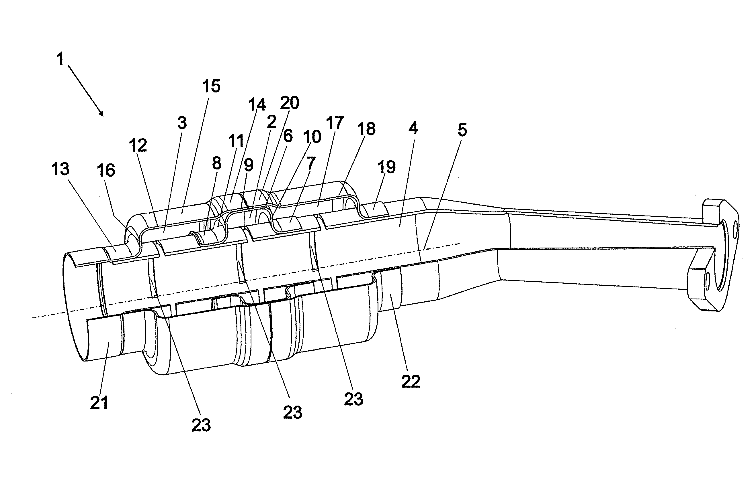
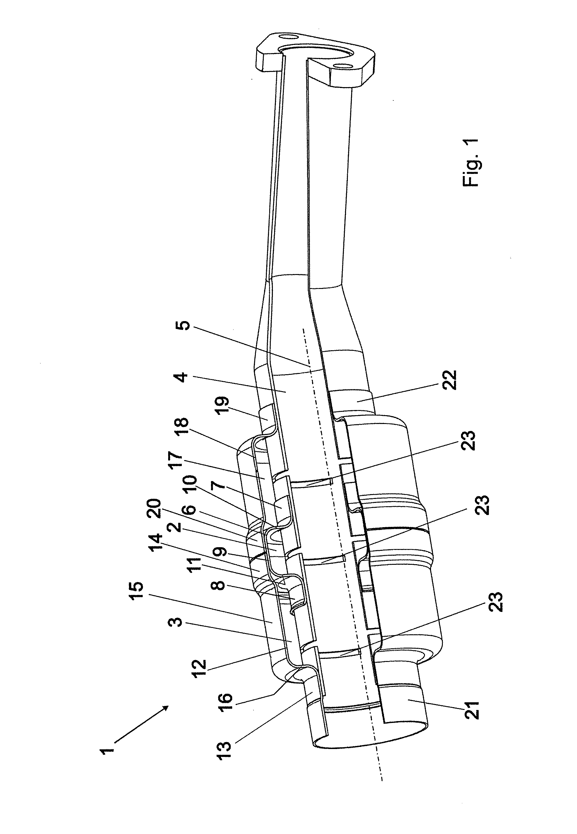
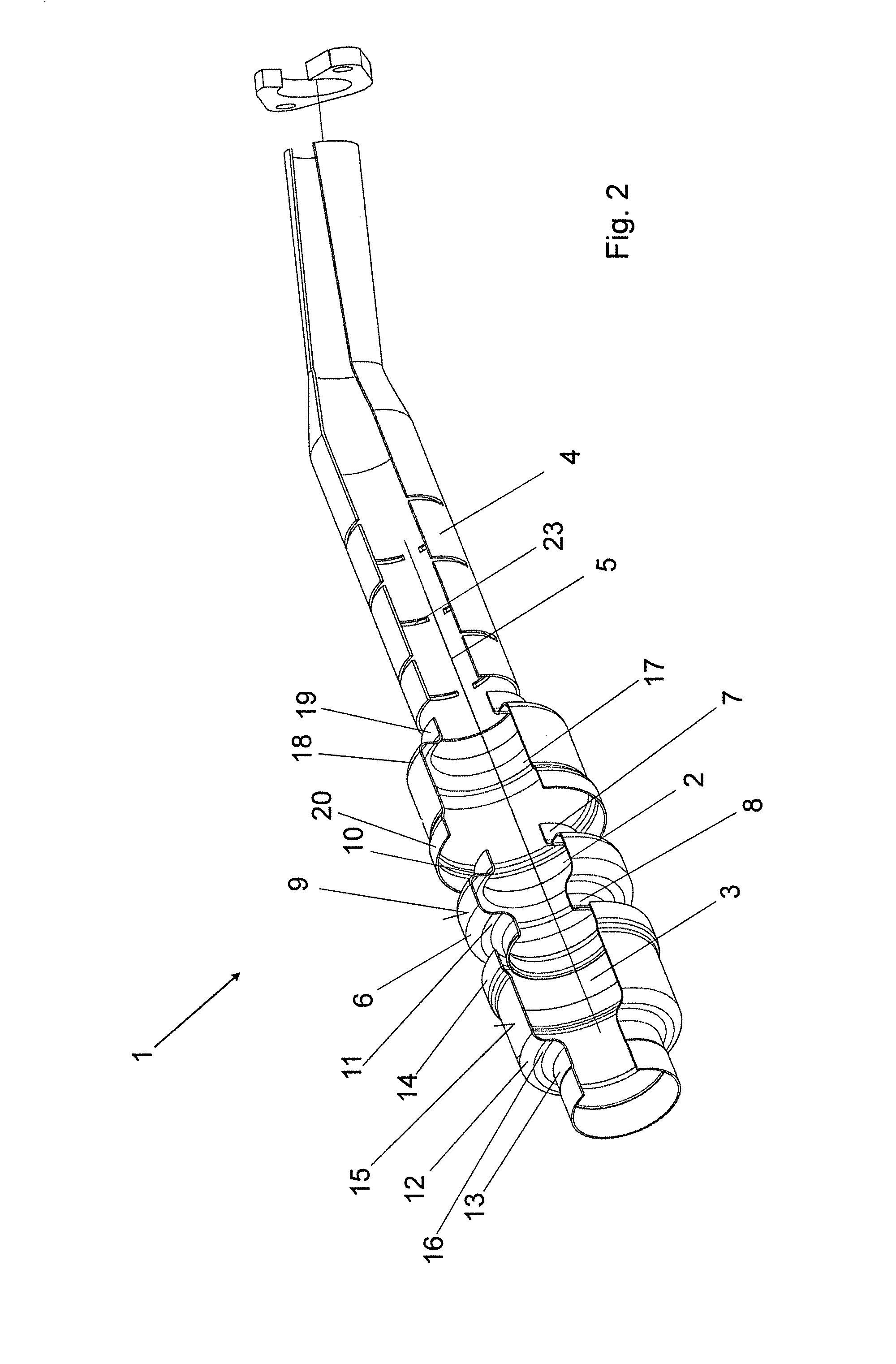
[0025]A resonator 1 for lowering airborne and solid-borne sound essentially comprises a first annular chamber 2, a second annular chamber 3 and an inner pipe 4.

[0026]The first annular chamber 2 is arranged coaxial to a resonator longitudinal axis 5 and has an essentially U-shaped circumferential wall 6 which at both ends transitions into cylindrical end pieces 7, 8. The U-shaped wall 6 has an outer wall 9 running parallel to the resonator longitudinal axis 5, said outer wall being limited by two ring-shaped side walls 10, 11 arranged perpendicular to the resonator longitudinal axis 5. The outer wall 9 transitions into the end pieces 7, 8 by way of the side walls 10, 11.

[0027]The second annular chamber 3 has an L-shaped circumferential wall 12 coaxial to the resonator longitudinal axis 5, which L-shaped circumferential wall, at its end facing away from the first annular chamber 2, transitions into a cylindrical end piece 13. At its end 14 facing the first annular chamber 2, the L-sha...


PUM


Abstract

A resonator (1) has at least first and second annular chambers (2, 3, 17) arranged between inlet and outlet pieces (22, 21). An inner pipe (4) extends between the inlet piece (22) and the outlet piece (21) and has wall holes (23) that connect to the annular chambers (2, 3, 17). The first annular chamber (2) has a U-shaped circumferential wall (6) coaxial to the resonator longitudinal axis (5) and transitions at both ends to engage the inner pipe (4). The second annular chamber (3) has an L-shaped circumferential wall (12) coaxial to the resonator longitudinal axis (5). An end of the L-shaped circumferential wall remote from the first annular chamber (2) transitions into a cylindrical end piece (13), and an opposite end of the L-shaped circumferential wall lies on part of the outer wall (9) of the first annular chamber (2) extending parallel to the resonator longitudinal axis (5).

Description

BACKGROUND[0001]1. Field of the Invention[0002]The invention relates to a resonator for lowering airborne sound and solid-borne sound, comprising at least two annular chambers arranged between an inlet piece and an outlet piece and comprising an inner pipe, which is arranged at least between the inlet piece and the outlet piece and which has wall holes as a connection to the adjacent annular chambers.[0003]2. Description of the Related Art[0004]When exhaust gas turbochargers, for example, are used in conjunction with internal combustion engines, undesirable flow-generated noises result as a consequence of engine speeds, imbalances and disruptions caused by production-related warping. These flow-generated noises are lowered across a broad spectrum by appropriate resonators or dampers. In particular, the resonators or dampers are arranged between the turbocharger and the internal combustion engine or between the turbocharger and an air cooler arranged upstream of the internal combusti...

Claims


Application Information

Patent Timeline
Patent Type & Authority Applications(United States)
IPC IPC(8): F02M35/12
CPCF02M35/1266F02M35/1261F02M35/1283F16L55/033F16L55/052
Inventor GRIESWALD, ANDREFISCHER, JENS
Owner UMFOTEC
Why Eureka
Try Eureka