
Heat transfer baffle arrangement for fuel-burning water heater

a technology for fuel-burning water heaters and baffles, which is applied in indirect heat exchangers, fire-tube steam boilers, lighting and heating apparatus, etc. it can solve the problems of increasing the residence time of combustion by-products within, adding to the overall cost of water heaters, and undetectable pressure drop, so as to promote heat transfer and increase the residence time

Active Publication Date: 2016-07-14
RHEEM MFG CO
View PDF14 Cites 12 Cited by
  • Summary
  • Abstract
  • Description
  • Claims
  • Application Information

AI Technical Summary

Benefits of technology

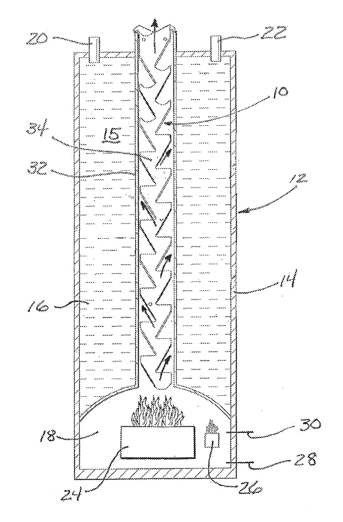
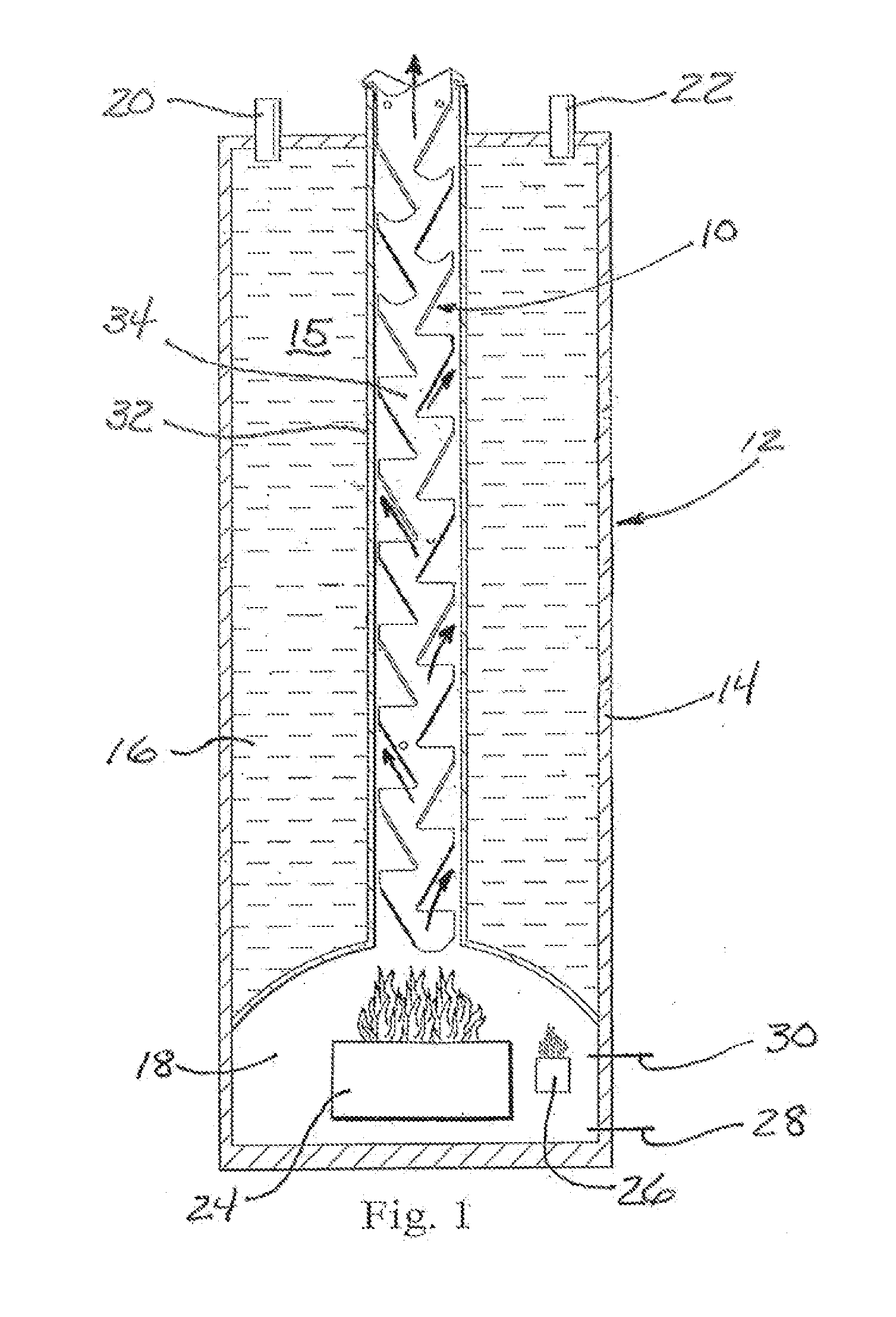
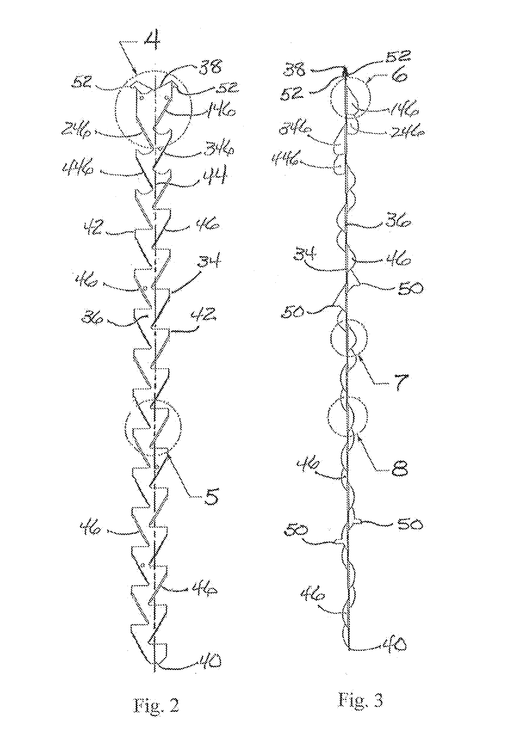
The present invention relates to a device that improves heat transfer in a water storage chamber by using a baffle arrangement in the exhaust flue. The baffle arrangement comprises an elongate base and a plurality of exhaust-directing fins spaced along the centerline of the base. The fins deflect combustion by-products outwardly and increase the time they stay in the exhaust flue, promoting heat exchange. The fins have varying configurations and surface areas to control the pressure drop in the exhaust flue. Basically, the baffle arrangement helps transfer heat from the combustion by-products to the water in the water storage chamber.

Problems solved by technology

Because the natural chimney effect of rising combustion by-products within an exhaust flue provides relatively inefficient heat exchange to the surrounding water within a water heater storage tank, it has become commonplace to provide a baffle arrangement within the exhaust flues of fuel-burning water heaters to interrupt natural laminar flow of the by-products and thereby increase residence time of combustion by-products within the exhaust flue to obtain increased heat transfer to the surrounding water.
While such baffle arrangements are generally effective to accomplish greater heat exchange than in water heaters without such baffle arrangements, known baffle arrangements have disadvantages.
Many known baffle arrangements require welding of individual component parts which undesirably add to the overall cost of water heaters.
Other baffle arrangements impose an undesirably higher pressure drop across the height of the exhaust flue.
Especially in water heaters that rely upon a natural upward thermal draft for exhaustion of combustion by-products, the hydrostatic pressure naturally occurring along the height of the exhaust flue may be quite small, and accordingly, a baffle arrangement imposing a greater pressure drop can impede proper exhaust of combustion by-products and risk a dangerous build up of carbon dioxide in the ambient environment surrounding the water heater.

Method used


Image

  • Heat transfer baffle arrangement for fuel-burning water heater
  • Heat transfer baffle arrangement for fuel-burning water heater
  • Heat transfer baffle arrangement for fuel-burning water heater

Examples


Embodiment Construction

[0021]Referring now to the accompanying drawings, the present invention is herein illustrated and described in a representative contemplated embodiment installed in a typical form of residential fuel-burning storage-tank water heater. As the present invention has applicability and utility for use in any of numerous differing forms of fuel-burning storage-tank water heaters, the water heater shown in the accompanying drawings and described herein is only schematically and generically depicted, it being intended and to be explicitly understood that the present invention is not limited to the structure, operation or form of the depicted water heater. The water heater is illustrated and described herein merely as representative of the environment in which the present invention is contemplated for use, so as to provide an enabling disclosure and understanding of the present invention. Likewise, the baffle arrangement of the present invention as depicted in the accompanying drawings and d...


PUM


Abstract

A baffle arrangement disposed within the exhaust flue of a fuel-burning water heater promotes heat transfer from exhausted combustion by-products to the water storage chamber. The baffle arrangement has an elongate planar base and plural exhaust-directing fins spaced along opposite sides of the base. Each fin is a planar body extending perpendicularly from the base at an acute upward angle from a longitudinal centerline to a respective side of the base. The fins deflect combustion by-products laterally outwardly within the flue to promote heat transfer. The fins are of selected configurations generally increasing in surface area upwardly along the planar base for selectively controlling pressure drop within the exhaust flue. Hanger tabs project outwardly from the upper end of the base to suspend the baffle arrangement within the flue. The planar base, hanger tabs and exhaust-directing fins are formed integrally from a unitary body of sheet metal.

Description

FIELD OF THE INVENTION[0001]The present invention relates generally to water heaters and especially to exhaust flue systems used in fuel-burning water heaters, such as water heaters which burn natural gas or propane gas. More particularly, the present invention relates to baffle arrangements used in the exhaust flues of fuel-burning water heaters to promote heat transfer to the body of water being heated.BACKGROUND OF THE INVENTION[0002]Tank-style water heaters generally comprise a water storage container or tank with water inlet and outlet connections and with a thermostatically controlled heating source to heat a body of contained water to, and maintain the water at, a predetermined temperature. Electricity or natural or propane gas are the most common heat sources used for both residential and commercial water heaters.[0003]In electric water heaters, the heating element is commonly submerged within the water tank to apply heat directly to the water. By contrast, gas-fueled water ...

Claims


Application Information

Patent Timeline
Patent Type & Authority Applications(United States)
IPC IPC(8): F24H1/20F23M9/10F23M9/00
CPCF24H1/205F23M9/10F23M9/003F24H9/0026F28F1/40F28F13/12F28D7/106F28D20/0034F28D2021/0024F28F2009/222Y02E60/14
Inventor ZHANG, QIANYIN, JIANGFLATNESS, GARYGIBBONS, DAVID
Owner RHEEM MFG CO
Learn More