Eureka AIR delivers breakthrough ideas for toughest innovation challenges, trusted by R&D personnel around the world.

Fixed-focus lens

a fixed-focus lens and lens body technology, applied in the field of lenses, can solve the problems of large volume of lenses, relatively complex mechanism design, and prone to thermal drift phenomenon of conventional mini-projectors on the market, and achieve the effect of high temperature tolerance and low manufacturing cos

Active Publication Date: 2016-07-14
CORETRONIC
View PDF1 Cites 22 Cited by
  • Summary
  • Abstract
  • Description
  • Claims
  • Application Information

AI Technical Summary

Benefits of technology

The invention is a fixed-focus lens with low manufacturing cost and high temperature tolerance. It satisfies specific requirements for a wide field of view and large aperture while maintaining high resolution imaging. The lens uses materials that inhibit thermal drift to prevent performance degradation from temperature changes. These features make the fixed-focus lens ideal for use in various optical devices.

Problems solved by technology

On the other hand, the conventional mini projectors on the market are prone to produce a thermal drift phenomenon because the limited heat dissipation due to restrictions of the volume of the mini projector.
Such architecture requires a relatively complex mechanism design in which a volume of the lens is larger.

Method used


Image

  • Fixed-focus lens
  • Fixed-focus lens
  • Fixed-focus lens

Examples


Embodiment Construction

[0038]In the following detailed description of the preferred embodiments, reference is made to the accompanying drawings which form a part hereof, and in which are shown by way of illustration specific embodiments in which the invention may be practiced. In this regard, directional terminology, such as “top,”“bottom,”“front,”“back,” etc., is used with reference to the orientation of the Figure(s) being described. The components of the invention can be positioned in a number of different orientations. As such, the directional terminology is used for purposes of illustration and is in no way limiting. On the other hand, the drawings are only schematic and the sizes of components may be exaggerated for clarity. It is to be understood that other embodiments may be utilized and structural changes may be made without departing from the scope of the invention. Also, it is to be understood that the phraseology and terminology used herein are for the purpose of description and should not be ...


PUM

PropertyMeasurementUnit
Lengthaaaaaaaaaa
Poweraaaaaaaaaa
Refractive indexaaaaaaaaaa

Abstract

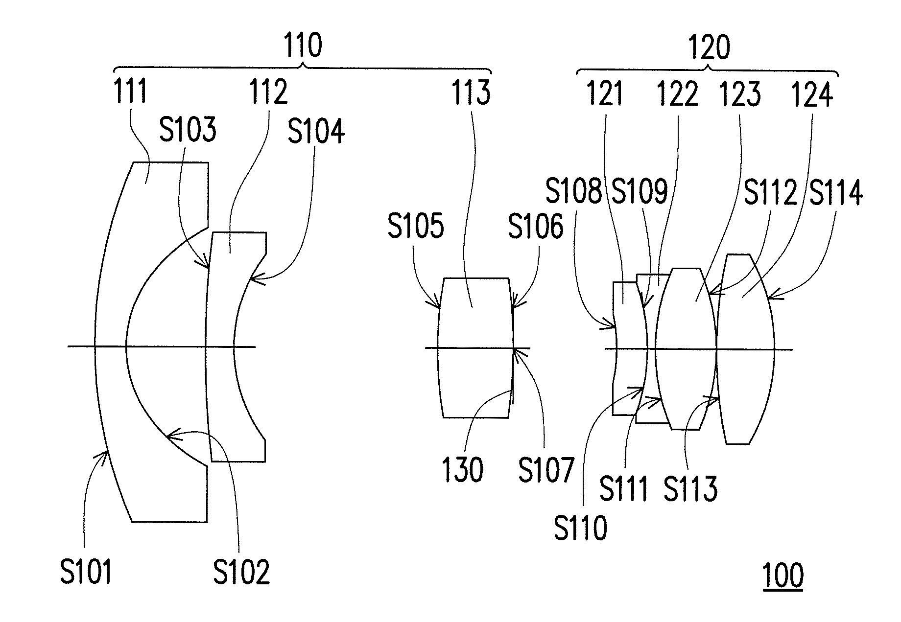
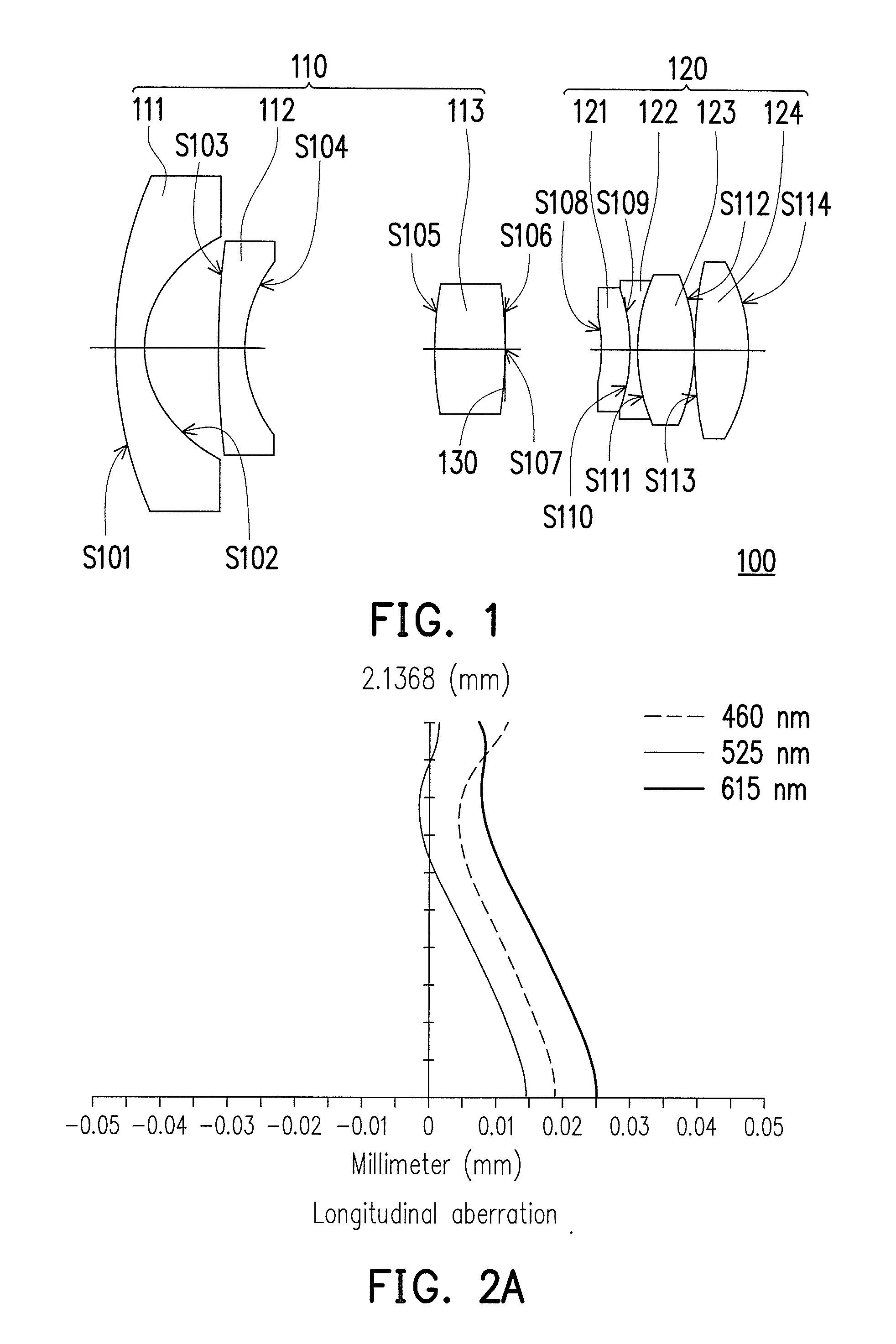
A fixed-focus lens including a first lens group, a second lens group and an aperture stop is provided. The first lens group has a positive refractive power, and includes a first lens, a second lens and a third lens arranged in sequence from a magnified side to a reduced side. The second lens group has a positive refractive power, and includes a fourth lens, a fifth lens, a sixth lens and a seventh lens arranged in sequence from the magnified side to the reduced side. A product of a refractive power and a slope of a refractive index changing with a temperature change of any one lens of the second lens group is P×(dn / dt), and a sum of P×(dn / dt) of the lenses of the second lens group is less than 0. The aperture stop is disposed between the first lens group and the second lens group.

Description

CROSS-REFERENCE TO RELATED APPLICATION[0001]This application claims the priority benefit of Taiwan application serial no. 104100761, filed on Jan. 9, 2015. The entirety of the above-mentioned patent application is hereby incorporated by reference herein and made a part of this specification.BACKGROUND OF THE INVENTION[0002]1. Field of the Invention[0003]The invention generally relates to a lens, and more particularly to a fixed-focus lens.[0004]2. Description of Related Art[0005]With advances in optical-electronic technologies, image apparatuses such as digital video cameras (DVC), projectors and digital cameras (DC) have been widely applied in daily life. Lens is one of core elements in the image apparatus, and configured to display images clearly on a screen or a charge coupled device (CCD). In case the image apparatus are applied in specific fields, a wide angle lens is adopted to increase a field of view (FOV). For instance, the wide angle lens is required in use of a car back-u...

Claims


Application Information

Patent Timeline
IPC IPC(8): G02B9/60G02B1/04G02B27/00G02B13/18
CPCG02B9/60G02B27/0025G02B1/041G02B13/18G02B13/04G02B7/028
Inventor KUO, TAO-HUNGLIN, TZU-YUANWEI, CHING-CHUANCHENG, CHUAN-TE
Owner CORETRONIC
Why Eureka
Eureka Blog
Learn More