3D Microscopy With Illumination Engineering

a technology of illumination engineering and microscope, applied in the field of microscope/imaging assembly with illumination engineering, can solve the problems of mutual exclusiveness of cases, high cost of accessories, and inability to meet the needs of all microscopes

Inactive Publication Date: 2016-07-14
UNIV OF CONNECTICUT
View PDF5 Cites 37 Cited by
  • Summary
  • Abstract
  • Description
  • Claims
  • Application Information

AI Technical Summary

Benefits of technology

[0011]In exemplary embodiments, the assemblies, methods and equipment disclosed herein use a spatial light modulator (SLM), such as a liquid crystal display (LCD) or digita...

Problems solved by technology

These methods typically require either a motorized stage or focus mechanism, both of which can be expensiv...

Method used


Image

  • 3D Microscopy With Illumination Engineering
  • 3D Microscopy With Illumination Engineering
  • 3D Microscopy With Illumination Engineering

Examples


example 1

Microscopy Illumination Engineering Using a Low-Cost Liquid Crystal Display

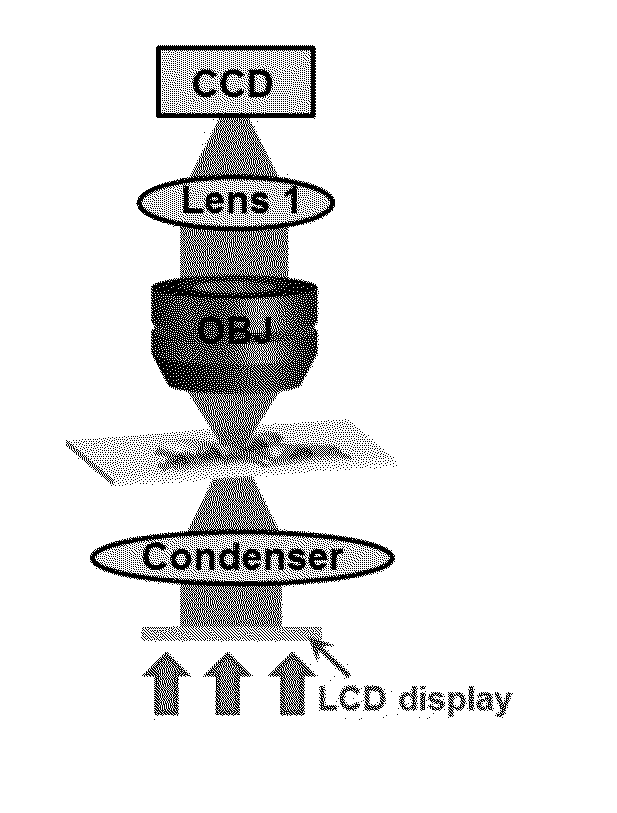
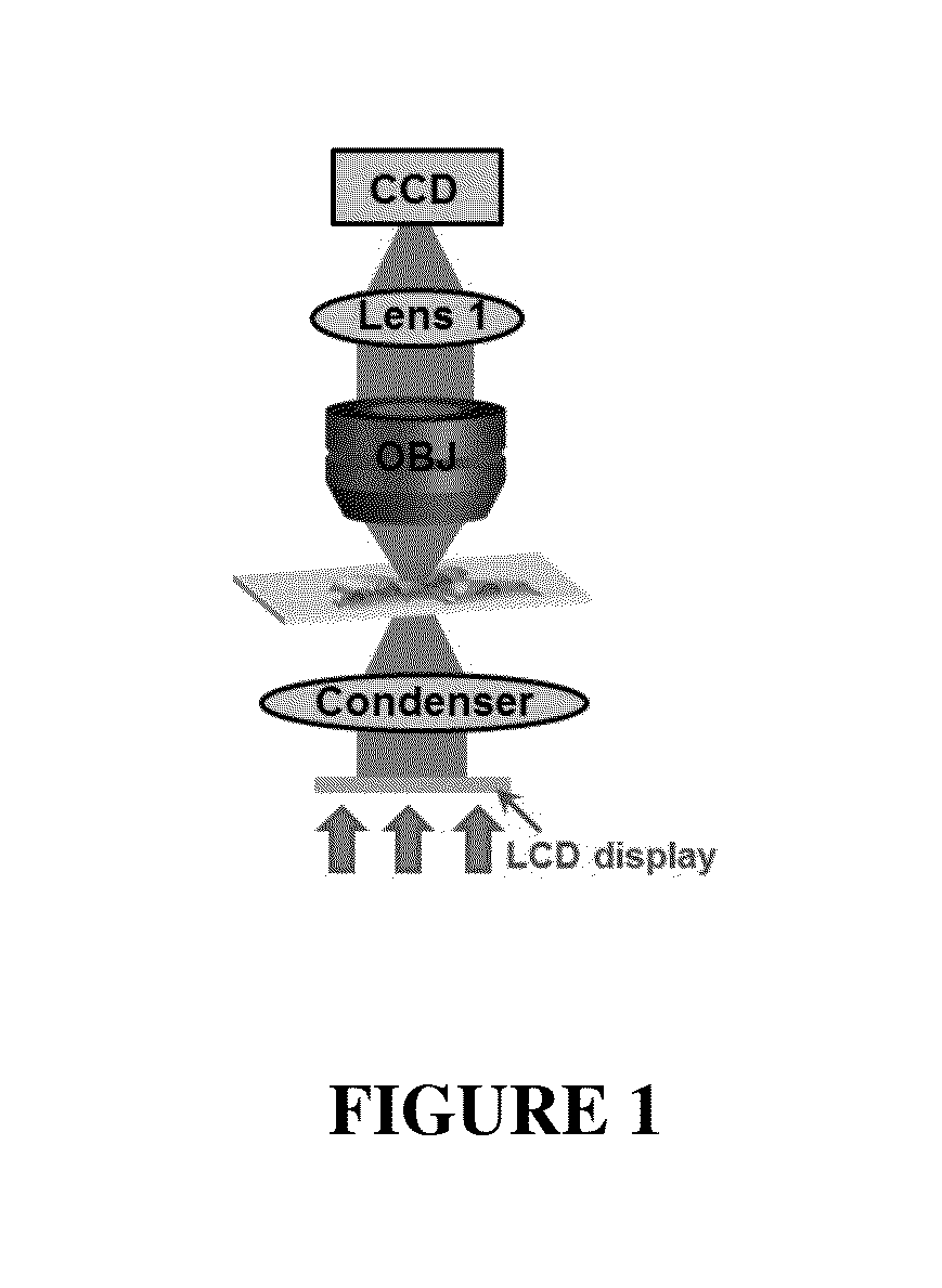
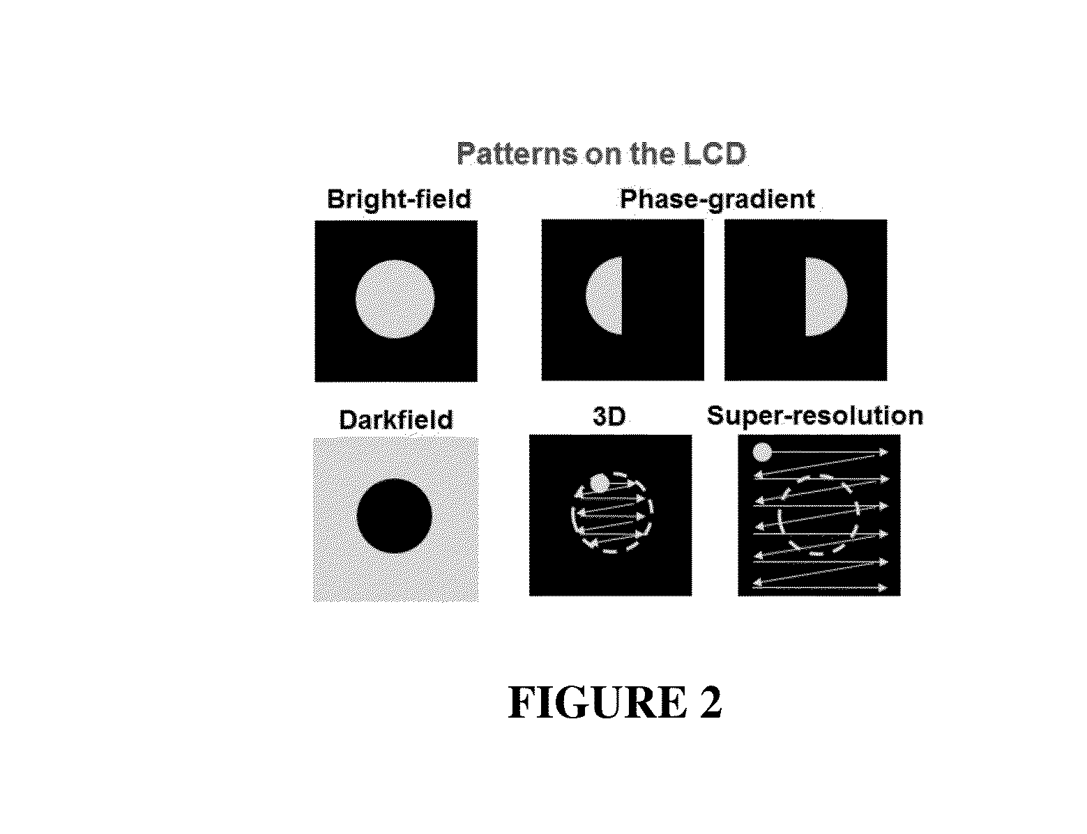
[0049]In general, illumination engineering is important for obtaining high-resolution, high-quality images in microscope settings. In a typical microscope, the condenser lens provides sample illumination that is uniform and free from glare. The associated condenser diaphragm can be manually adjusted to obtain the optimal illumination numerical aperture. In this Example, a programmable condenser lens for active illumination control is disclosed. In an exemplary prototype setup, an inexpensive liquid crystal display was utilized as a transparent spatial light modulator, and it was placed at the back focal plane of the condenser lens. By setting different binary patterns on the display, one can actively control the illumination and the spatial coherence of the microscope platform. As such, the use of this scheme for multimodal imaging, including bright-field microscopy, darkfield microscopy, phase-contrast micro...

example 2

Illumination Control / Computational Imaging: Multimodal Microscopy Using a Low-Cost Liquid Crystal Display

[0077]Traditional condenser lenses should be physically adjusted to meet the needs of different microscopy modalities. But a low-cost liquid crystal display (LCD), serving as a transparent spatial light modulator in a microscopy platform, enables active illumination control for multiple imaging approaches.

[0078]The condenser lens system, typically consisting of a high-numerical-aperture (NA) lens and a diaphragm at the lens' back focal plane, is an important component of a traditional microscope. The diaphragm allows for manual adjustment of the illumination aperture, which is important because various microscopy techniques require vastly different condenser illumination. Meeting these requirements is currently a matter of physically adjusting the condenser diaphragm, or else using specialized condenser apertures.

[0079]As noted above, various microscopy techniques require vastl...

example 3

[0100]This Example provides various embodiments to the imaging assemblies discussed above. As noted in Examples 1 and 2 above, FIG. 9 shows the imaging assembly having a light source 1, a condenser 3, the sample 4, the objective or other detection optics 5, the tube lens or camera adapter 8, and the imaging sensor 10. In this embodiment, the SLM 2 (e.g., digitally controlled LCD or DMD 2) is positioned between the light source 1 and the condenser 3 (e.g., between the light source 1 and the backfocal plane of the condenser 3) for imaging purposes (e.g., for 3D tomographic imaging using computational image reconstruction with brightfield or fluorescence illumination; for illumination modulation and 3D tomography).

[0101]In an alternative embodiment and as shown in FIG. 10, the imaging assembly can include the SLM 2 (e.g., digitally controlled LCD or DMD 2) positioned at the backfocal plane of the detection optic element 5 (e.g., the objective or other detection optics 5) for imaging pu...


PUM


Abstract

The present disclosure provides improved microscopic imaging techniques, equipment and systems. More particularly, the present disclosure provides advantageous microscopy assemblies with illumination engineering (e.g., 3D microscopy assemblies with illumination engineering), and related methods of use. Disclosed herein is an imaging technique/assembly that uses a spatial light modulator (“SLM”) for 3D tomographic imaging with brightfield or fluorescence illumination that can also be utilized for bright-field, dark-field, phase-contrast, and super-resolution microscopy. Disclosed herein are methods and instrumentation/assemblies having preferred uses for 3D tomographic imaging, and phase-contrast and super-resolution imaging. The present disclosure advantageously provides for assemblies and methods configured to create 3D tomographic images by way of acquiring a series of images with varied angle illumination using a SLM and computational reconstruction that substantially eliminates the need to move the sample. The disclosed assemblies and methods are also able to acquire bright-field, dark-field, various contrast, and super-resolution images.

Description

CROSS-REFERENCE TO RELATED APPLICATIONS[0001]This application claims priority to Provisional Application Ser. No. 62 / 102,906 filed Jan. 13, 2015, the contents of which is hereby incorporated by reference in its entirety.FIELD OF THE DISCLOSURE[0002]The present disclosure relates generally to the field of microscopic imaging techniques, equipment and systems and, more particularly, to microscopy / imaging assemblies with illumination engineering (e.g., three-dimensional microscopy / imaging assemblies with illumination engineering).BACKGROUND OF THE DISCLOSURE[0003]In general, equipment and procedures in the field of microscopic imaging are known.[0004]However, it is noted that capturing 3D images of samples generally requires the movement of the microscope stage or the optics to acquire images at various focal positions. These methods typically require either a motorized stage or focus mechanism, both of which can be expensive and not available for all microscopes.[0005]Moreover, known ...

Claims


Application Information

Patent Timeline
IPC IPC(8): G02B21/00H04N5/225
CPCG02B21/004H04N5/2256G02B13/0095G02B21/0076G02B21/0032G02B21/125G02B21/14G02B21/16G02B21/362G02B27/58H04N23/56
Inventor ZHENG, GUOAN
Owner UNIV OF CONNECTICUT
Why Eureka
Try Eureka