Point of sale (pos) docking station system and method for a mobile barcode scanner gun system with mobile tablet device or stand alone mobile tablet device

Active Publication Date: 2016-07-14
RETAIL TECH
View PDF0 Cites 27 Cited by
  • Summary
  • Abstract
  • Description
  • Claims
  • Application Information

AI Technical Summary

Benefits of technology

[0026]Further enhancing the usability of this configuration, a secondary “tilting” feature at the point of integration between the Stand-Alone Mobile Tablet and the Upper Housing Assembly allows for the Stand-Alone Mobile Tablet itself to tilt ninety degrees down “toward” the user or “away” from the user on a secondary tilting armature. This feature is designed for t

Problems solved by technology

Other mobile tablet devices can be inserted into a fixed point of sale workstation and used as the main processor and data input device; however, the immediate portability of the mobile tablet device is not available.
Consequently, the mobile tablet device cannot operate both within a fixed point of sale (POS) terminal and removed from the POS terminal seamlessly and in the middle of store system transactions.
This lack of operational portability impedes the employee of the retail establishment from servicing its customers when mobility is required to checkout customers in a dynamic retail store environment, such as outdoor garden centers, high customer traffic periods of time or kiosk sales in a variety of retail environments, both indoors and outdoors.
Further, while performing inventory management functions out on the retail floor with typical wireless scan guns, these mobile devices cannot be immediately inserted into a fixed POS terminal and perform a customer POS sales transaction.
Then these mobile

Method used


Image

  • Point of sale (pos) docking station system and method for a mobile barcode scanner gun system with mobile tablet device or stand alone mobile tablet device
  • Point of sale (pos) docking station system and method for a mobile barcode scanner gun system with mobile tablet device or stand alone mobile tablet device
  • Point of sale (pos) docking station system and method for a mobile barcode scanner gun system with mobile tablet device or stand alone mobile tablet device

Examples


Embodiment Construction

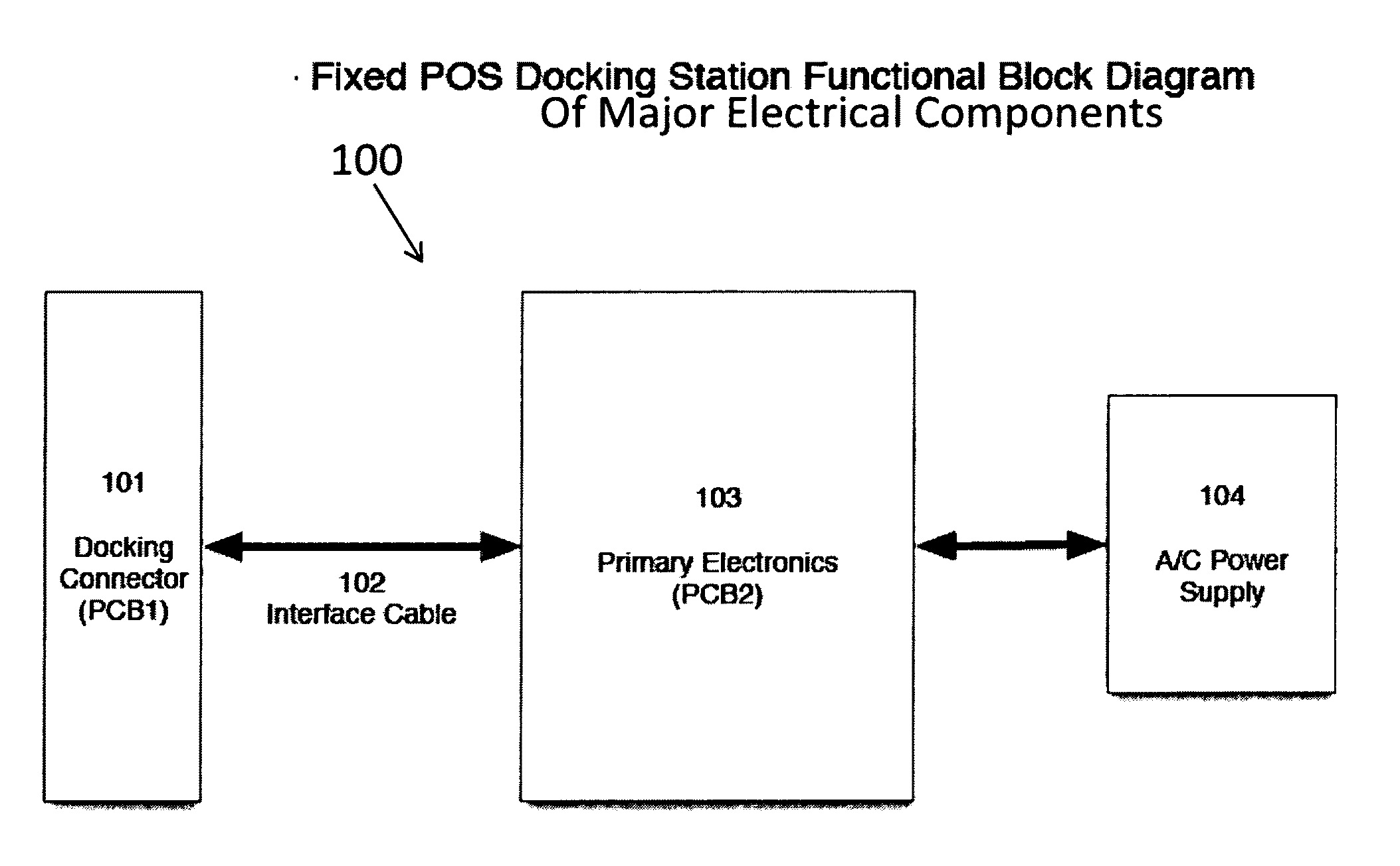
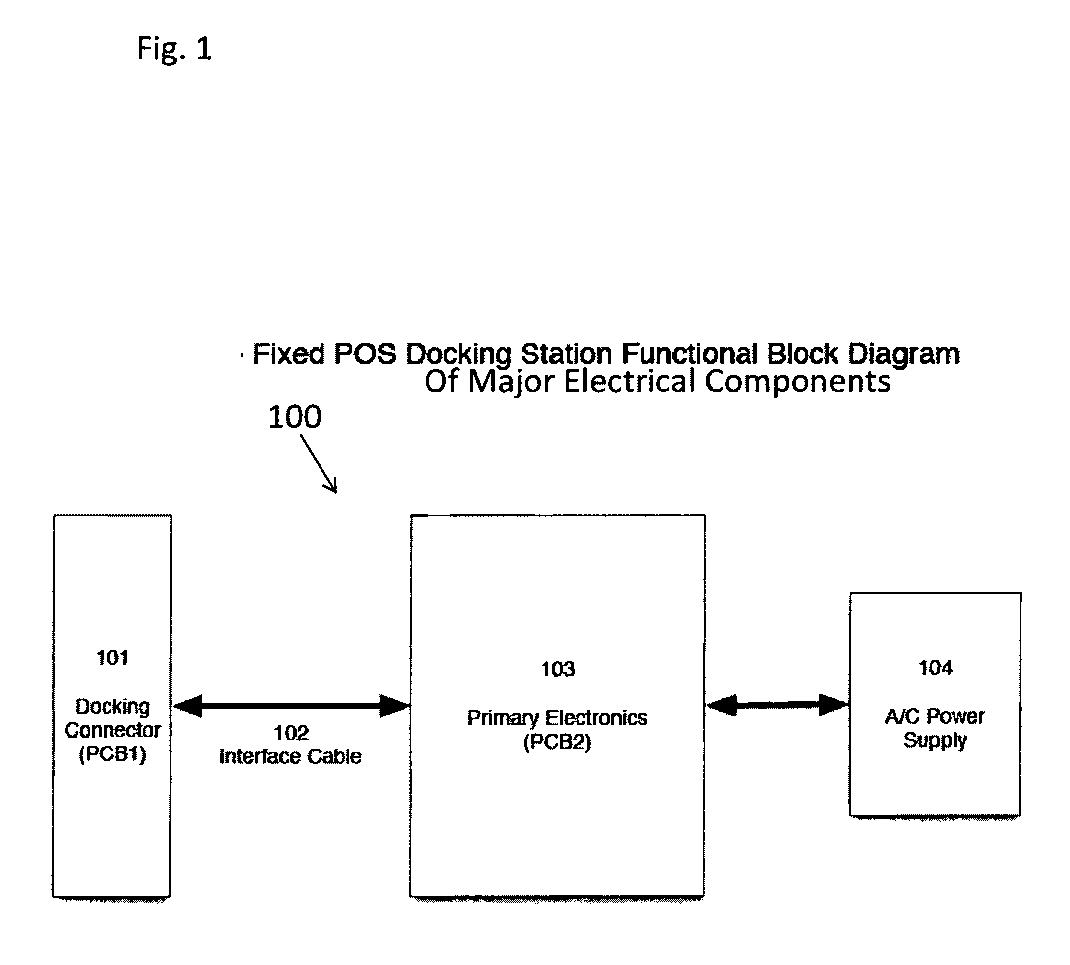
[0050]The subject invention is directed toward the mobile barcode scanner gun system or stand-alone mobile tablet transforming into a fixed point of sale (POS) terminal through the use of the subject invention fixed POS docking station. Advantageously, the mobile barcode scanner gun system or stand-alone mobile tablet, customized for use as a mobile store systems terminal, is transformed into an integrated fixed POS terminal while being docked into the fixed POS docking station. This transformation is instantaneous, and is effected without consideration to any operation being performed on the mobile barcode scanner gun system or stand-alone mobile tablet.

[0051]As used herein, the term “fixed” means a docking station wherein the portable mobile device is docked or placed for charging, providing access to a power supply, providing a docking base, and to peripheral devices or auxiliary features. The docking station itself may be on a fixed terminal or on a mobile terminal or cart with ...


PUM


Abstract

A POS docking station for a mobile scanner gun system or mobile tablet (tablet) processes POS sales transactions. An upper housing assembly enclosure houses the “tablet” in a “cradle fashion” fitting snuggly around the “tablet”, providing stability and form fit integration. An electrical connector integrates the upper housing to a printed circuit board (PCB1) to the “tablet”. A base housing assembly includes a scanner trigger button, a base mounting plate, a primary printed circuit board (PCB2) with at least one USB, Ethernet, Serial port, scan switch interface and an external power supply port, and a tilting and rotational mechanism. PCB1 is connected to PCB2 through an interface cable connecting the POS docking station to the “tablet”. USB, Ethernet, Serial ports, scan switch interface and power supply within the base housing assembly are fully operable to the “tablet”, and can be connected to a variety of store systems POS peripheral devices.

Description

CROSS-REFERENCE TO RELATED APPLICATIONS[0001]This is a continuation-in-part application of U.S. patent application Ser. No. 14 / 121,323, filed Aug. 19, 2014, entitled “Mobile Barcode Scanner Gun System With Mobile Tablet Device Having A Mobile POS And Enterprise Resource Planning Application For Customer Checkout / Order Fulfillment And Real Time In Store Inventory Management For Retail Establishment”, which in turn is a divisional application of U.S. patent application Ser. No. 13 / 783,089, filed Mar. 1, 2013, entitled “Mobile Barcode Scanner Gun System With Mobile Tablet Device Having A Mobile POS And Enterprise Resource Planning Application For Customer Checkout / Order Fulfillment And Real Time In Store Inventory Management For Retail Establishment”, now U.S. Pat. No. 8,856,033, which in turn is a nonprovisional application of U.S. Prov. Pat. App. No. 61 / 751,906, filed Jan. 13, 2013, entitled “Mobile Barcode Scanner Gun System With Mobile Tablet Device Having A Mobile POS And Enterpri...

Claims


Application Information

Patent Timeline
IPC IPC(8): G06Q20/20G06Q20/34G06Q20/40G06K7/10
CPCG06Q20/208G06Q20/401G06Q20/34G06K7/10821G07G1/0081G06Q20/204G06K7/109
Inventor HICKS, BRUCE J.MCWHIRTER, BRIAN K.
Owner RETAIL TECH
Why Eureka
Try Eureka