
Forming iii-v device structures on (111) planes of silicon fins

a technology of silicon fins and device structures, applied in the field of silicon fins, can solve the problems of inability to meet the requirements of iiiv material low defect density, inability to meet the requirements of iiiv material density,

Inactive Publication Date: 2016-07-14
INTEL CORP
View PDF3 Cites 16 Cited by
  • Summary
  • Abstract
  • Description
  • Claims
  • Application Information

AI Technical Summary

Benefits of technology

The patent text describes a method for integrating materials such as gallium nitride onto silicon surfaces for use in high voltage and RF devices. The challenge is to overcome the lattice mismatch between the two materials, which can result in surface cracks and inhibit the use of III-V materials on Si (100) for device fabrication. The patent proposes a method that involves forming a III-V device layer on a silicon fin structure, adding a polarizing inducing layer, and then adding a III-V based source / drain material on the III-V device layer to form a III-V based source / drain material on the terminal ends of the silicon fin. This structure allows for high voltage SoC applications such as RF power and power management integrated circuit (PMIC) applications. The patent also describes a method for forming microelectronic structures, such as silicon nanofin structures, on silicon substrates for use in high voltage and RF device applications.

Problems solved by technology

This integration involves fabrication challenges that may arise due to the mismatch in lattice properties between the two materials.
This lattice mismatch, which may be near forty two percent, may cause epitaxial growth of low defect density III-V materials to become prohibitive.
Additionally, the large thermal mismatch between gallium nitride and silicon (which is about one hundred and sixteen percent) coupled with conventional high growth temperatures for gallium nitride, can result in the formation of surface cracks on epitaxial layers, thus inhibiting the use of III-V materials on Si (100) for device fabrication.

Method used


Image

  • Forming iii-v device structures on (111) planes of silicon fins
  • Forming iii-v device structures on (111) planes of silicon fins
  • Forming iii-v device structures on (111) planes of silicon fins

Examples


Embodiment Construction

[0007]In the following detailed description, reference is made to the accompanying drawings that show, by way of illustration, specific embodiments in which the methods and structures may be practiced. These embodiments are described in sufficient detail to enable those skilled in the art to practice the embodiments. It is to be understood that the various embodiments, although different, are not necessarily mutually exclusive. For example, a particular feature, structure, or characteristic described herein, in connection with one embodiment, may be implemented within other embodiments without departing from the spirit and scope of the embodiments. In addition, it is to be understood that the location or arrangement of individual elements within each disclosed embodiment may be modified without departing from the spirit and scope of the embodiments. The following detailed description is, therefore, not to be taken in a limiting sense, and the scope of the embodiments is defined only...


PUM

PropertyMeasurementUnit
thicknessaaaaaaaaaa
thicknessaaaaaaaaaa
crystal structureaaaaaaaaaa

Abstract

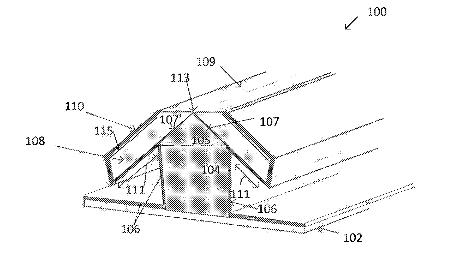
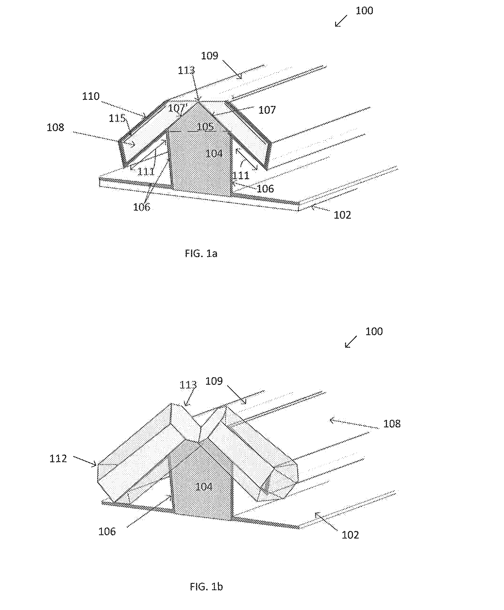
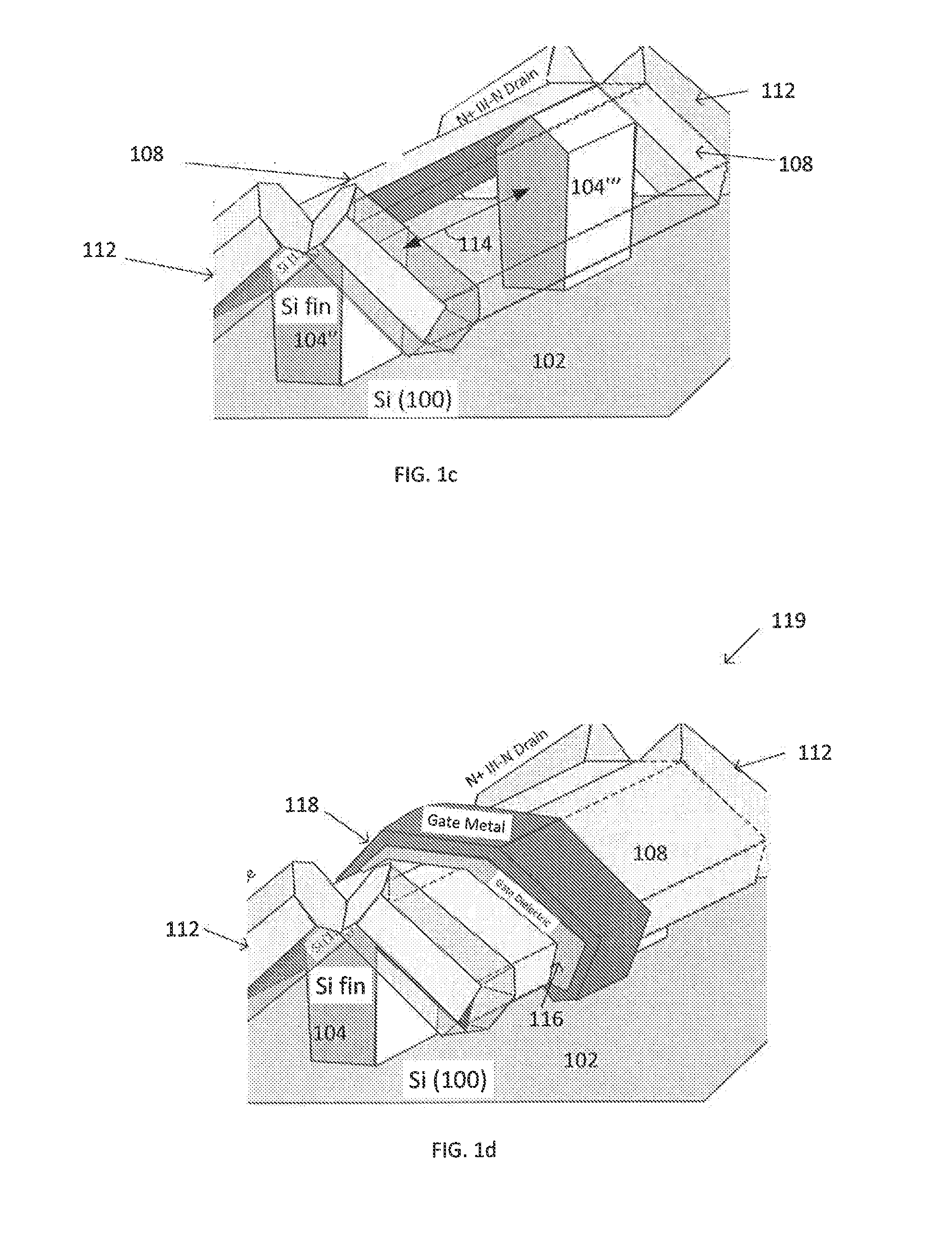
Methods of forming high voltage (111) silicon nano-structures are described. Those methods and structures may include forming a III-V device layer on (111) surface of a silicon fin structure, forming a 2DEG inducing polarization layer on the III-V device layer, forming a source / drain material on a portion of the III-V device layer on terminal ends of the silicon fin. A middle portion of the silicon fin structure between the source and drain regions may be removed, and backfilled with a dielectric material, and then a gate dielectric and a gate material may be formed on the III-V device layer.

Description

BACKGROUND OF THE INVENTION[0001]Integration of materials, such as gallium nitride, onto (100) silicon surfaces (100) is highly desired for such applications as) high voltage and RF devices for System on chip (SoC) technology, as well as for complementary metal oxide silicon (CMOS) applications. This integration involves fabrication challenges that may arise due to the mismatch in lattice properties between the two materials. This lattice mismatch, which may be near forty two percent, may cause epitaxial growth of low defect density III-V materials to become prohibitive. Additionally, the large thermal mismatch between gallium nitride and silicon (which is about one hundred and sixteen percent) coupled with conventional high growth temperatures for gallium nitride, can result in the formation of surface cracks on epitaxial layers, thus inhibiting the use of III-V materials on Si (100) for device fabrication.BRIEF DESCRIPTION OF THE DRAWINGS[0002]While the specification concludes wit...

Claims


Application Information

Patent Timeline
Patent Type & Authority Applications(United States)
IPC IPC(8): H01L29/786H01L29/04H01L29/51H01L29/66H01L29/423H01L29/49H01L27/108H01L29/06H10B12/00
CPCH01L29/78696H01L27/10826H01L27/10879H01L29/045H01L29/0676H01L29/517H01L29/78681H01L29/66742H01L29/42392H01L29/4908H01L29/78618H01L29/66462H01L29/7786H01L29/0657H01L29/2003H01L21/02381H01L21/0243H01L21/02433H01L21/0245H01L21/02494H01L21/02516H01L21/0254B82Y10/00H01L29/775H01L29/0673H01L29/413H01L29/66795H01L29/7848H01L29/7853H01L29/785H10B12/36H10B12/056
Inventor DASGUPTA, SANSAPTAKTHEN, HAN WUIGARDNER, SANAZCHU-KUNG, BENJAMINRADOSAVLJEVIC, MARKOSUNG, SEUNG HOONCHAU, ROBERT
Owner INTEL CORP
Learn More