Recirculation arrangement and method for a high temperature cell system

Active Publication Date: 2016-07-14
CONVION OY
View PDF5 Cites 11 Cited by
  • Summary
  • Abstract
  • Description
  • Claims
  • Application Information

AI Technical Summary

Benefits of technology

[0013]A recirculation arrangement for a high temperature fuel cell system or electrolysis cell system is disclosed, each cell in the system having an anode, a cathode, and an electrolyte between the anode and the cathode, the recirculation arrangement comprising: at least one ejector for recirculating a fraction of gas exhausted from the anode side and for accomplishing a desired flow rate of the recirculated flow, the ejector having at least one nozzle; means for providing at least one primary feedstock fluid to said nozzle of the ejector, which nozzle has a convergent-divergent flow channel through which the fluid will expand from an initial higher pressure to a lower pressure; means for providing at least one supplementary fluid to said nozzle of the ejector; means for regulating a respective ratio of at least part of the fluids of the ejector to maintain a desired motive flow and pressure at the nozzle of said ejector in order to accomplish the desired recirculated flow rate; and means for cutting off the supplementary fluid when level of system loading i

Problems solved by technology

Due to fixed geometry of the jet-ejector, these system topologies have a limited capability for controlling the re-circulation ratio and the resultant Oxygen-to Carbon (O/C) ratio at reformer or stack inlet and therefore can include compensating means such as an external water feed and a steam generator in the system to ensure adequate but not excessive steam content at fuel cell stacks.
Insufficient steam flow rate can lead to disadvantageous and potentially irreversible formation of soot in the components throughout the fuel side of the system.
On the other hand, excessive recirculation and

Method used


Image

  • Recirculation arrangement and method for a high temperature cell system
  • Recirculation arrangement and method for a high temperature cell system
  • Recirculation arrangement and method for a high temperature cell system

Examples


Embodiment Construction

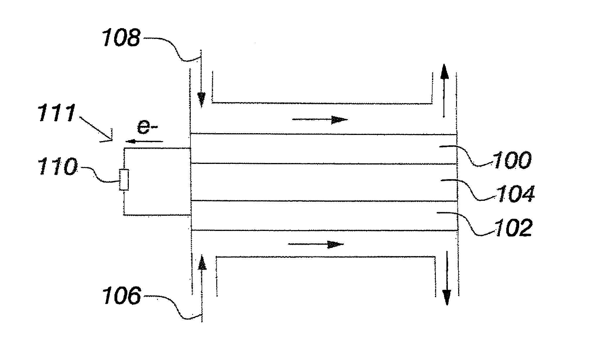
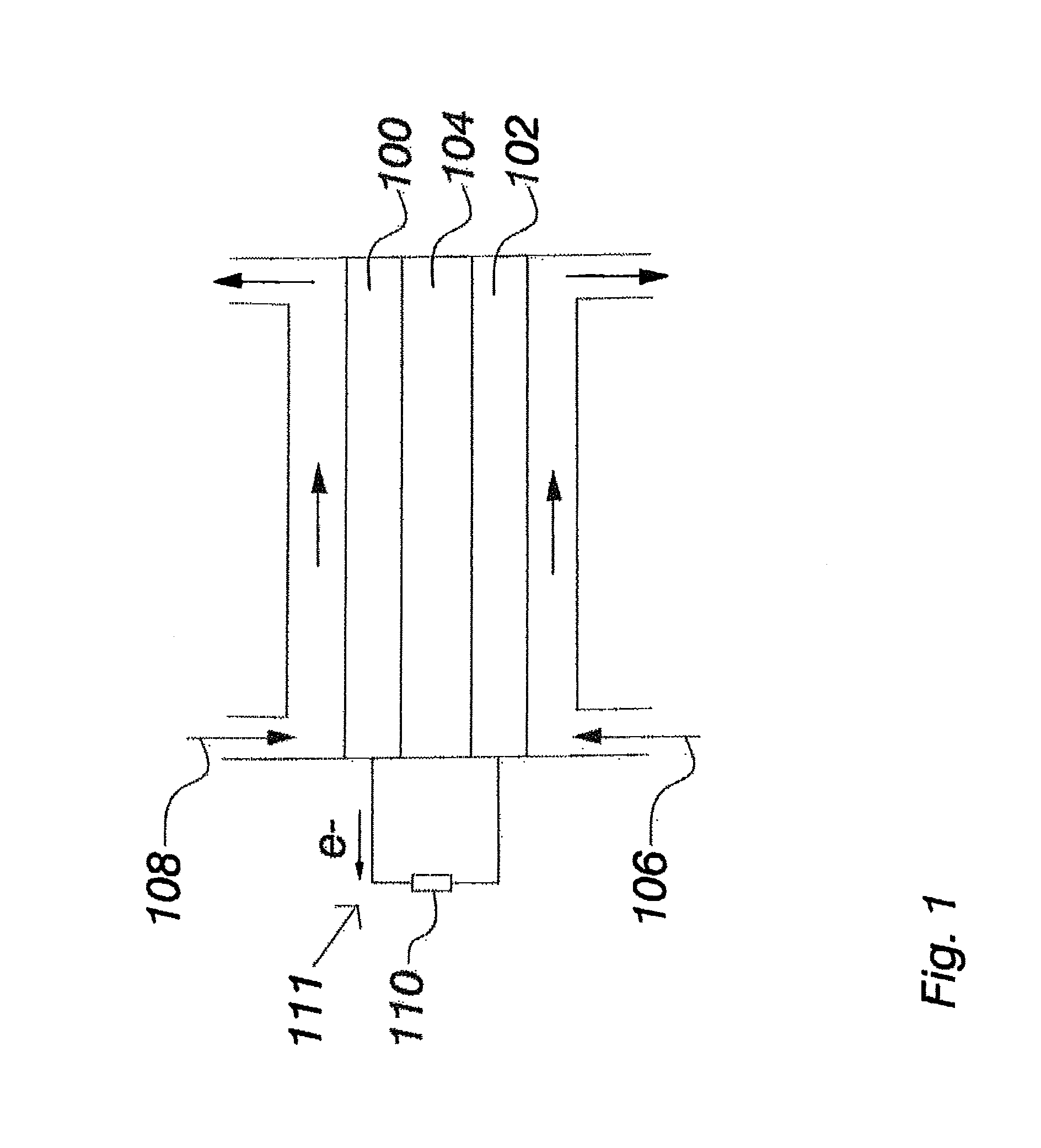
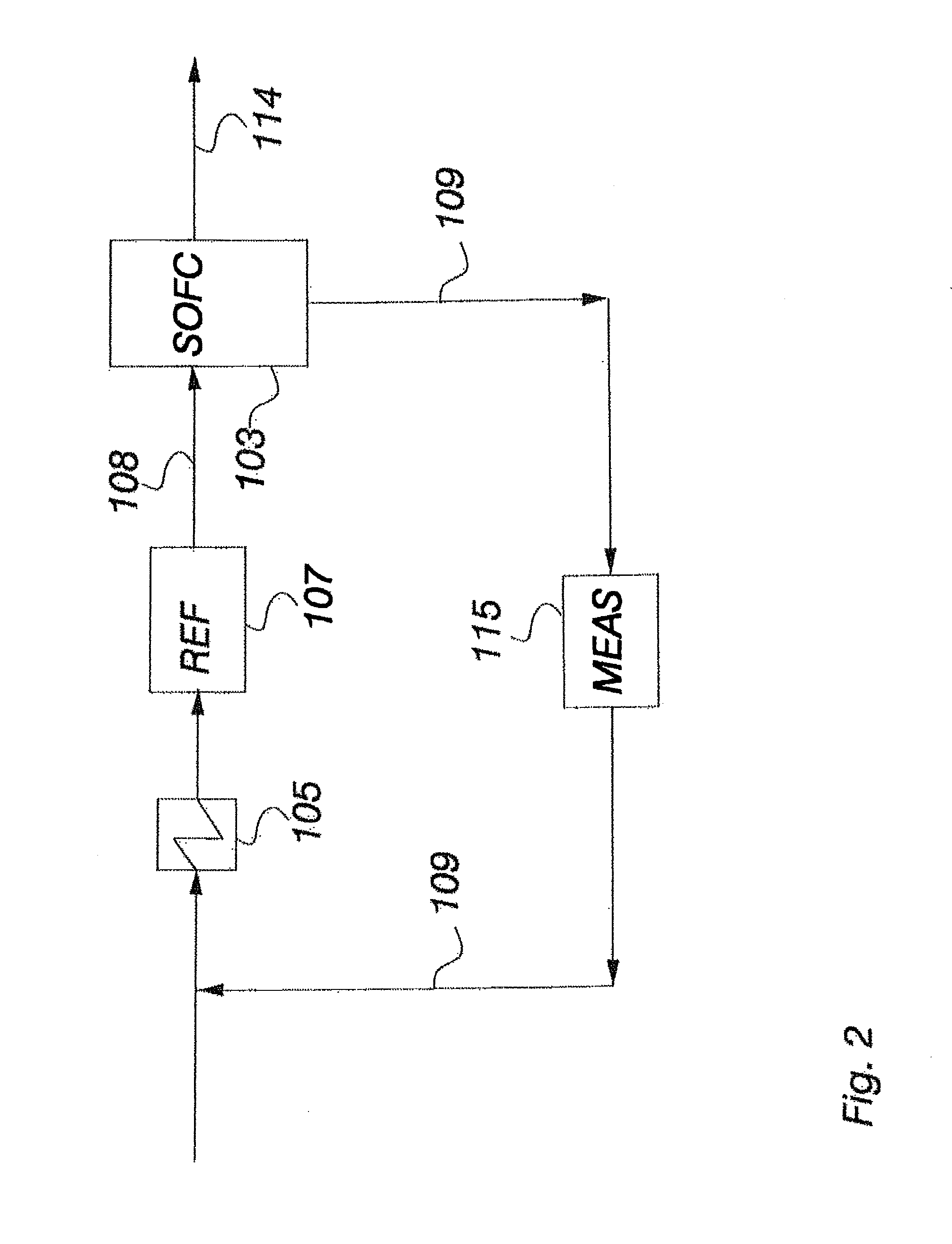
[0022]With reference to the figures, a recirculation arrangement for an SOFC or an SOEC system is disclosed which can enable effective reactant utilization in the system and thus result in a high system performance, and ensure optimized thermal and compositional conditioning in the anode side in all modes of operation, which can result in an improved feasibility and lowered complexity of a SOFC or SOEC system. This is achieved by a recirculation arrangement for a high temperature fuel cell system or electrolysis cell system, each cell in the system having an anode, a cathode, and an electrolyte between the anode and the cathode, the recirculation arrangement having at least one ejector for recirculating a fraction of gas exhausted from the anode side. The recirculation arrangement includes the ejector for accomplishing desired flow rate of the recirculated flow, the ejector having at least one nozzle, and the recirculation arrangement having means for providing at least one primary ...


PUM


Abstract

A method and system for high temperature fuel cell system or electrolysis cell are disclosed which include recirculating a fraction of gas exhausted from at least one of sides an anode side and a cathode side; accomplishing a desired flow rate of the recirculated flow by using an ejector via at least one primary feedstock fluid to a nozzle of the ejector, which nozzle has a convergent-divergent flow channel through which fluid is expanded from an initial higher pressure to lower pressure; providing supplementary fluid to the nozzle of the ejector; regulating respective ratio of the fluids of the ejector to maintain a desired motive flow and pressure at the nozzle of the ejector in order to accomplish desired recirculated flow rate; and cutting off the supplementary fluid when a level of system loading is the primary feedstock fluid alone maintains desired flow and pressure at ejector inlet.

Description

RELATED APPLICATION[0001]This application claims priority under 35 U.S.C. §120 to International Application PCT / FI2013 / 050918 which was filed on Sep. 23, 2013, designated the U.S. The content of each prior application is hereby incorporated by reference in its entirety.FIELD[0002]Most of the energy of the world is produced using oil, coal, natural gas or nuclear power. All these production methods have their specific issues as far as, for example, availability and friendliness to environment are concerned. As far as the environment is concerned, especially oil and coal cause pollution when they are combusted. An issue with nuclear power is, at least, storage of used fuel.[0003]Especially because of the environmental problems, new energy sources, more environmentally friendly and, for example, having a better efficiency than the above-mentioned energy sources, have been developed. Fuel cell's, by means of which energy of fuel, for example biogas, is directly converted to electricity ...

Claims


Application Information

Patent Timeline
IPC IPC(8): H01M8/04089C25B15/08
CPCH01M8/04097H01M2008/1293C25B15/08F04F5/00H01M8/0618H01M8/04201Y02E60/50H01M8/04753
Inventor HAKALA, TUOMAS
Owner CONVION OY
Why Eureka
Try Eureka