Driver and image instrument

a technology of image instruments and drivers, applied in the direction of piezoelectric/electrostrictive device details, printers, camera focusing arrangement, etc., can solve the problems of motor oscillation and becoming uncontrollable, inability to drive with a predetermined drive amount or less for this minute driving, and complicated configuration and increase in siz

Active Publication Date: 2016-07-14
OM DIGITAL SOLUTIONS CORP
View PDF6 Cites 7 Cited by
  • Summary
  • Abstract
  • Description
  • Claims
  • Application Information

AI Technical Summary

Benefits of technology

[0014]According to a first aspect of the invention a driver comprises: a piezoelectric sheet including at least one first piezoelectric body portion which bends in a first direction, at least one second piezoelectric body portion which bends in a second direction that intersects at right angles with the first direction, and at least one connection portion which connects the first piezoelectric body portion and the second piezoelectric body portion; a fixing frame to which the at least one connection port...

Problems solved by technology

Thus, in an image instrument such as a camera, the configuration is complicated and increased in size.
However, the problem of these motors is that the motors oscillate and become uncontrollable in rapid driving at a predetermined ve...

Method used


Image

  • Driver and image instrument
  • Driver and image instrument
  • Driver and image instrument

Examples


first embodiment

[0042]Hereinafter, a first embodiment of the present invention will be described with reference to the drawings. In each of the drawings used in the following explanation, each component has a different scale so that the size of each component can be recognized on the drawings. The present invention is not limited solely to the number of components, the shapes of the components, the ratio of the sizes of the components, and the positional relation between the components shown in the drawings below.

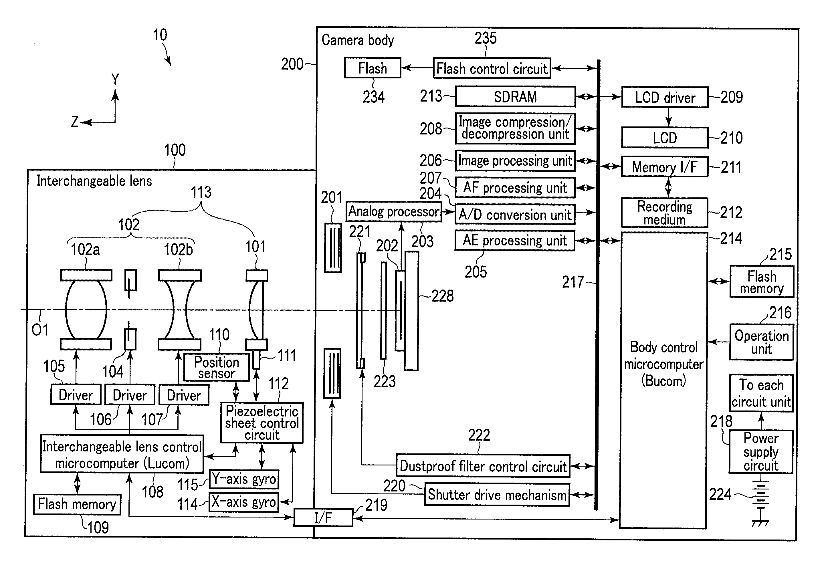
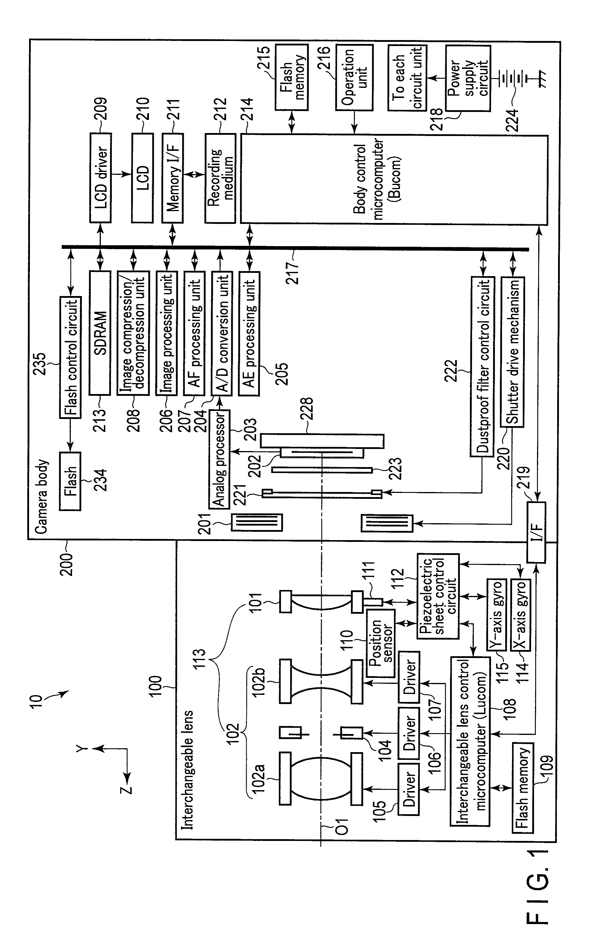
[0043]FIG. 1 shows a block diagram of a configuration example of a camera system (digital camera) 10 to which an operational device according to the present embodiment of the present invention is applied. In this camera system 10, a direction from a camera body 200 toward a subject is referred to as the front, and the opposite direction is referred to as the rear. An axis corresponding to an optical axis O1 of an optical system constituted by an interchangeable lens 100 is a Z-axis, and tw...

first modification

[0188]Now, a first modification of the present invention is described mainly in connection with the differences between the first modification and the first embodiment. FIG. 9 and FIG. 10 show a partly sectional view of a modification of the piezoelectric body portion of the piezoelectric sheet 311 different from the first embodiment shown in FIG. 5 to FIG. 8. FIG. 9 shows a sectional view corresponding to the sectional side taken along the line B-B shown in FIG. 5. FIG. 10 shows a sectional view corresponding to the sectional side view taken along the line C-C sheet shown in FIG. 5. Although the line C-C traverses two through-holes, to avoid complexity of the drawing in FIG. 5, only one through-hole is shown here, to simplify explanation.

[0189]The first drive piezoelectric layer 803 is formed by the sheets 800 of the L-polylactic acid. The second drive piezoelectric layer 804 is formed by the sheets 801 of the D-polylactic acid. The GND electrode 806 and the signal electrode 802 ar...

second modification

[0239]Now, a second modification of the present invention is described with reference to FIG. 18 and FIG. 19. The second modification is only different from the first embodiment in the structure of the piezoelectric sheet 111, so that the differences are described. FIG. 18 shows a partial development diagram corresponding to the part in the vicinity of the piezoelectric body portion 316db of the piezoelectric sheet 311 in FIG. 5 according to the first embodiment. FIG. 19 is a sectional side view taken along the line E-E in FIG. 18.

[0240]The piezoelectric sheet 311 according to the first embodiment does not include any detection piezoelectric layer provided to correspond to a detection electrode in the piezoelectric sheet control circuit 430 shown in FIG. 13. In the present second modification, a detection piezoelectric layer 810 is provided in the vicinity of a neutral surface of a bending portion of the piezoelectric body portion PZ. Thus, in the present second modification, if the...


PUM


Abstract

A driver includes a piezoelectric sheet, a fixing frame, a moving frame, and a control circuit. The piezoelectric sheet includes a first piezoelectric body portion which bends in a first direction, a second piezoelectric body portion which bends in a second direction that intersects at right angles with the first direction, and a connection portion which connects the first and second piezoelectric body portions. The fixing frame is fixed to the connection portion. The moving frame is supported on the first and second piezoelectric body portions. The control circuit applies voltage signals to the first and second piezoelectric body portions to bend the first and second piezoelectric body portions and which moves the moving frame in one of the first direction and the second direction or in a composite direction of the first direction and the second direction.

Description

CROSS-REFERENCE TO RELATED APPLICATIONS[0001]This application is a Continuation application of PCT Application No. PCT / JP2015 / 059159, filed Mar. 25, 2015 and based upon and claiming the benefit of priority from the prior Japanese Patent Application No. 2014-079660, filed Apr. 8, 2014, the entire contents of both of which are incorporated herein by reference.BACKGROUND OF THE INVENTION[0002]1. Field of the Invention[0003]The present invention relates to a driver and an image instrument which uses the driver, the driver driving a movable frame which is included a photographic lens and is driven for an image blur correction and focusing during imaging or which is included a camera and is a movable frame (moving frame, lens) holding a lens constituting the photographic lens.[0004]2. Description of the Related Art[0005]Recently, digital cameras which enable not only still image photography but also moving image photography have been on the market. When autofocus is performed in the photo...

Claims


Application Information

Patent Timeline
IPC IPC(8): H04N5/232H01L41/04H01L41/053H01L41/09H01L41/083
CPCH04N5/23287H01L41/0926H01L41/042H01L41/053H01L41/083G02B7/02G02B7/04G03B2205/0061G03B3/10G03B5/00H02N2/028G03B2205/0007H10N30/874H10N30/503H10N30/2042H10N30/857G02B27/646G02B7/09H04N23/687H10N30/50H10N30/88H10N30/204H10N30/802
Inventor KAWAI, SUMIO
Owner OM DIGITAL SOLUTIONS CORP
Why Eureka
Try Eureka