Airborne Surveillance Kite

a kite and surveillance technology, applied in the field of surveillance systems, can solve the problems of aerostat drawbacks, unsuitable, and large support staff for uav operation, and achieve the effect of improving the safety of passengers and crew, reducing the risk of accidents, and improving safety

Inactive Publication Date: 2016-07-21
BAILEY GLEN R
View PDF23 Cites 29 Cited by
  • Summary
  • Abstract
  • Description
  • Claims
  • Application Information

AI Technical Summary

Benefits of technology

[0006]A deployable airborne surveillance kite for flying in a wind over a surface includes a wing, a tail, and a spar coupling the wing to the tail. The kite further includes a thrust rotor mounted to the kite in a vertical orienta

Problems solved by technology

However, UAVs require a large support staff to operate and are not particularly well suited for small surveillance areas given the time and cost requirements in maintaining and operating them.
Aerostats have drawbacks, however.
The lifting gas helium is a dwindling rarity and is extremely expensive.
Aerostats can only be launched, flown, or brought down in limited wind conditions, demanding careful monitoring and accurate weather prediction.
Aerostats tend to lose buoyancy with time as gas permeates the balloon

Method used


Image

  • Airborne Surveillance Kite
  • Airborne Surveillance Kite
  • Airborne Surveillance Kite

Examples


Embodiment Construction

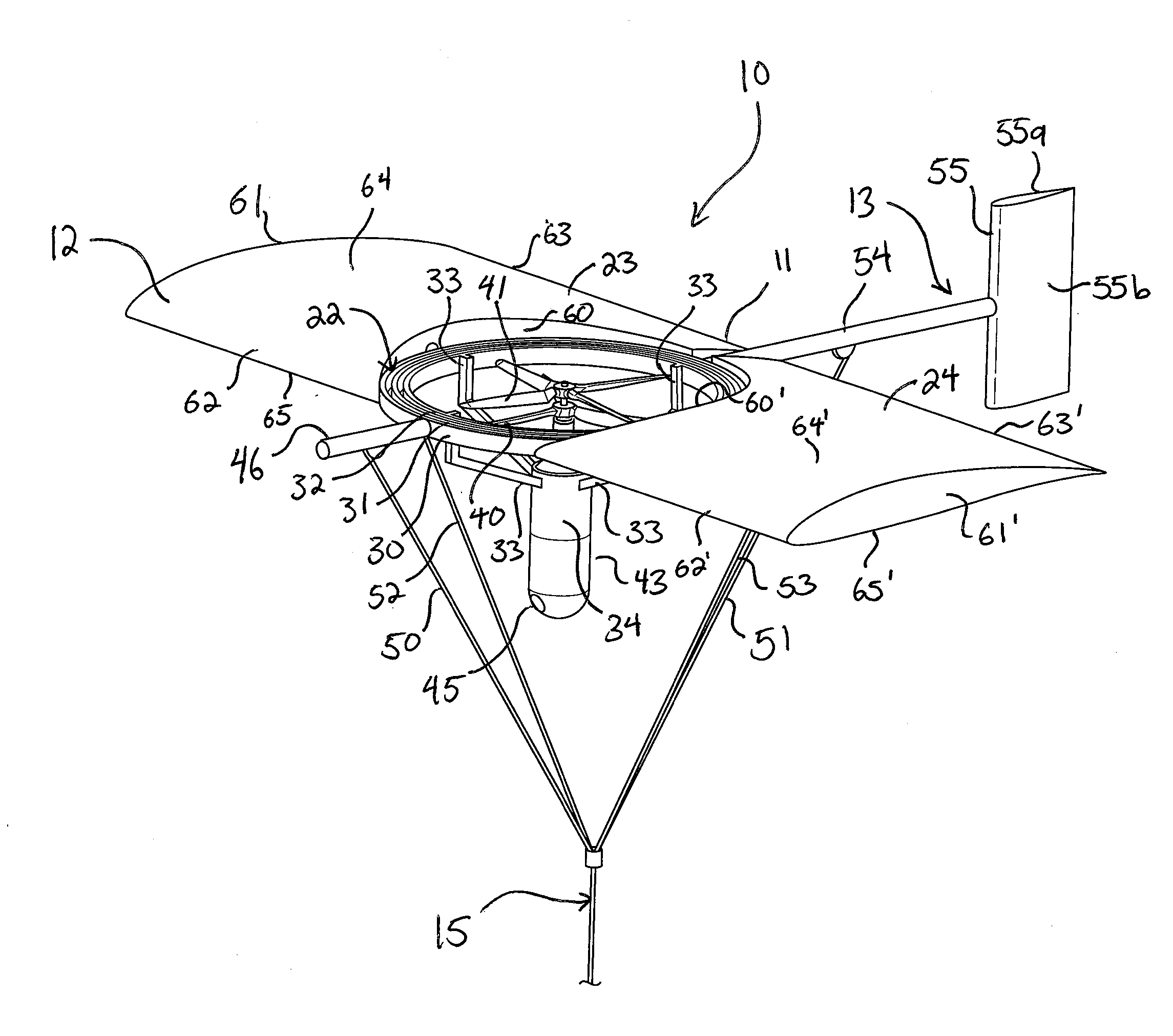
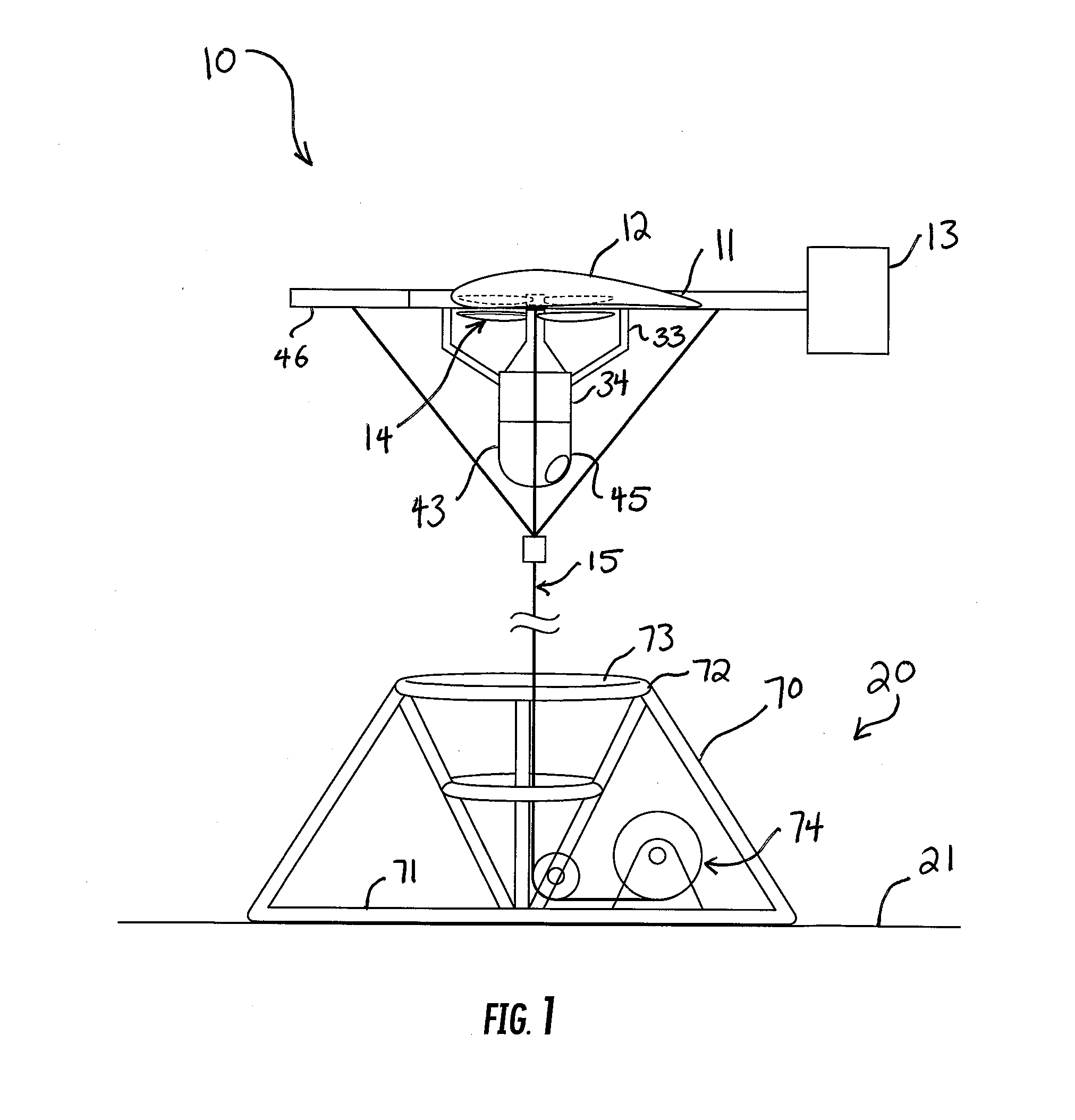
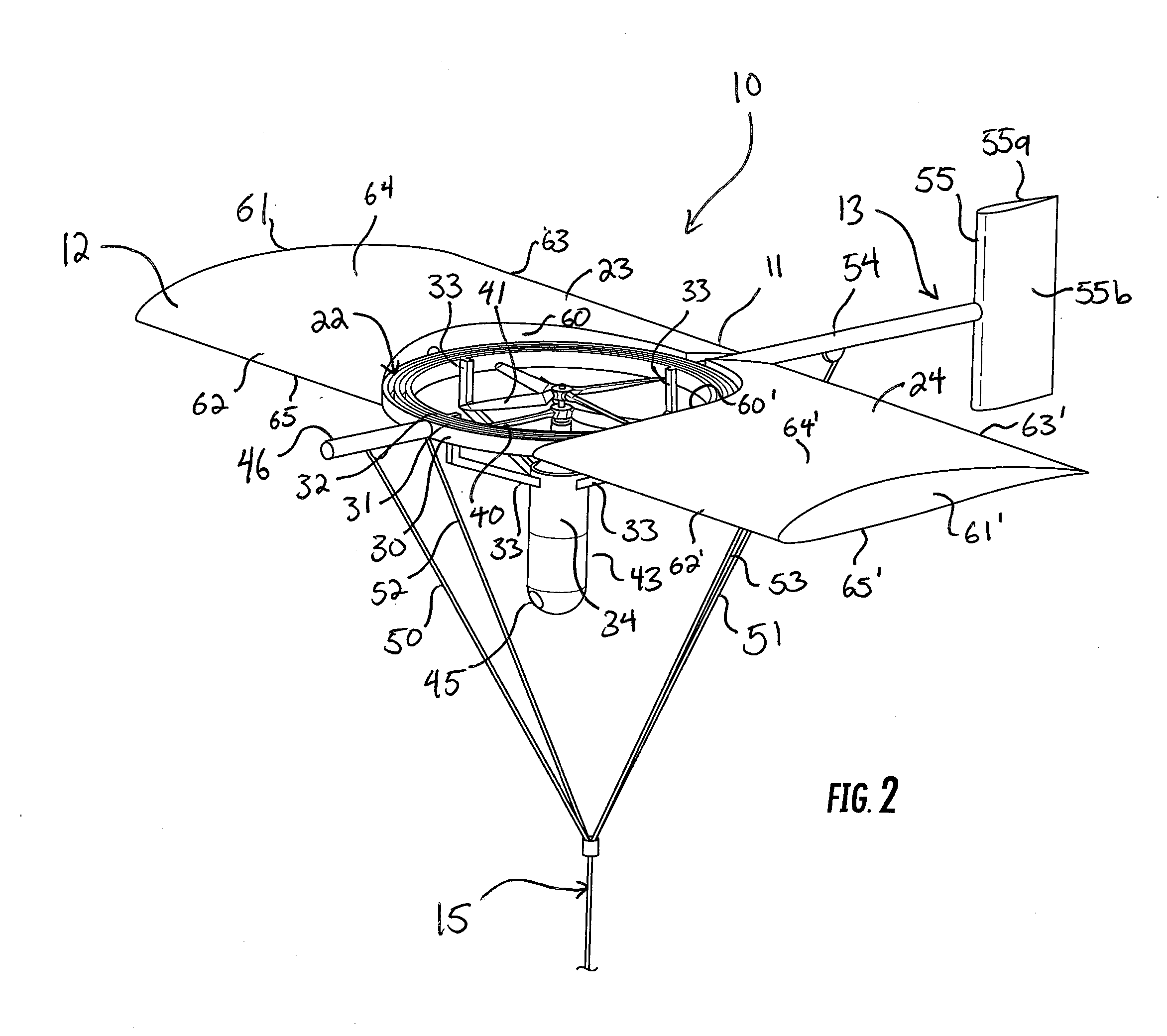
[0015]Reference now is made to the drawings, in which the same reference characters are used throughout the different figures to designate the same elements. FIG. 1 is a generalized side elevation view of a deployable, airborne surveillance system referred to as a “kite”10. As shown throughout the drawings, the kite 10 is a tethered airborne surveillance system for providing remote surveillance of an area from a range of heights by collecting a variety of information and communicating such information to a receiver such as a ground base. Very basically, the kite 10 includes a framework 11, a large fixed wing 12, a tail 13, and a propeller assembly 14 providing vertical lift to the kite 10. The kite 10 is coupled, via a tether assembly 15, to a secure base or dock 20 to fix the kite 10 to a location 21 for surveillance of the location 21 and areas around the location 21. FIG. 1 shows kite 10 in a scale of its own, but not to scale with the dock 20. Additionally, the ether 15 is fores...


PUM


Abstract

A deployable airborne surveillance kite for flying in a wind over a surface includes a wing, a tail, and a spar coupling the wing to the tail. The kite further includes a thrust rotor mounted to the kite in a vertical orientation for providing vertical lift to the kite. A tether assembly extends from the kite to the surface and couples the kite to the surface providing downward resistance in opposition to the vertical lift provided by the thrust rotor.

Description

CROSS-REFERENCE TO RELATED APPLICATIONS[0001]This application claims the benefit of U.S. Provisional Application No. 62 / 105,964, filed Jan. 21, 2015, which is hereby incorporated by reference.FIELD OF THE INVENTION[0002]The present invention relates generally to surveillance systems, and more particularly to airborne surveillance systems.BACKGROUND OF THE INVENTION[0003]There are a variety of solutions for providing visual, radar, or other surveillance of an area. Unmanned aerial vehicles (“UAVs”) provide a highly mobile, versatile platform for airborne sensors. They can be operated from large offset distances to remain covert and provide access to a very wide area of surveillance coverage. However, UAVs require a large support staff to operate and are not particularly well suited for small surveillance areas given the time and cost requirements in maintaining and operating them. Further, fixed-wing UAVs can loiter only by circling an area, and single- and multi-copter UAVs have sho...

Claims


Application Information

Patent Timeline
IPC IPC(8): B64C39/02B64F3/02B64C3/00B64C27/08B64D17/00B64D27/24B64C27/06
CPCB64C39/022B64D27/24B64F3/02B64C27/06B64C2201/148B64D17/00B64C3/00B64C2201/127B64C2201/165B64C27/08B64C31/06B64U30/10B64U30/20B64U2201/202B64U2101/30
Inventor BAILEY, GLEN R.
Owner BAILEY GLEN R
Why Eureka
Try Eureka