Modular aircraft system

a module aircraft and aircraft technology, applied in the field of aviation, can solve the problems of not being able to provide other wing configurations, not being able to easily be removed, and generally not being modular in nature, so as to simplify the interconnection between the fuselage and the wings, simplify the wing construction, and reduce the aerodynamic lift

Active Publication Date: 2016-11-29
AL SABAH NASSER M
View PDF19 Cites 43 Cited by
  • Summary
  • Abstract
  • Description
  • Claims
  • Application Information

AI Technical Summary

Benefits of technology

[0015]The landing gear for the aircraft is preferably retractable, and incorporated in the single fuselage in order to simplify the wing construction for the various wing configurations and to simplify the interconnects between fuselage and wings. The fuselage also preferably contains an internal payload bay for weaponry, additional fuel, surveillance equipment such as cameras and/or other sensors, etc. The top of the fuselage further includes an aerodynamic brake located in front of the rearwardly situated engine module. The aerodynamic brake may be considered as a spoiler, i.e., a device “spoiling” or reducing the aerodynamic lift over the fuselage, as the fuselage is shaped or configured somewhat like a lifting body in order to enhance the aerodynamic performance of the modular aircraft. The spoiler is configured such that it does not induce engine flameout in the case of a turbojet engine, and is ...

Problems solved by technology

Such aircraft might also be used for reconnaissance, but only for shorter range missions due to the fuel consumption and relatively small onboard fuel capacity provided by the interior volume of the relatively small wings.
They were not readily removable, and no oth...

Method used


Image

  • Modular aircraft system
  • Modular aircraft system
  • Modular aircraft system

Examples


second embodiment

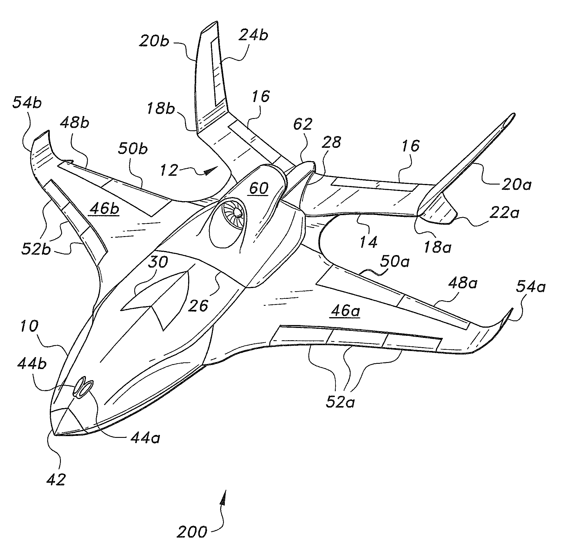
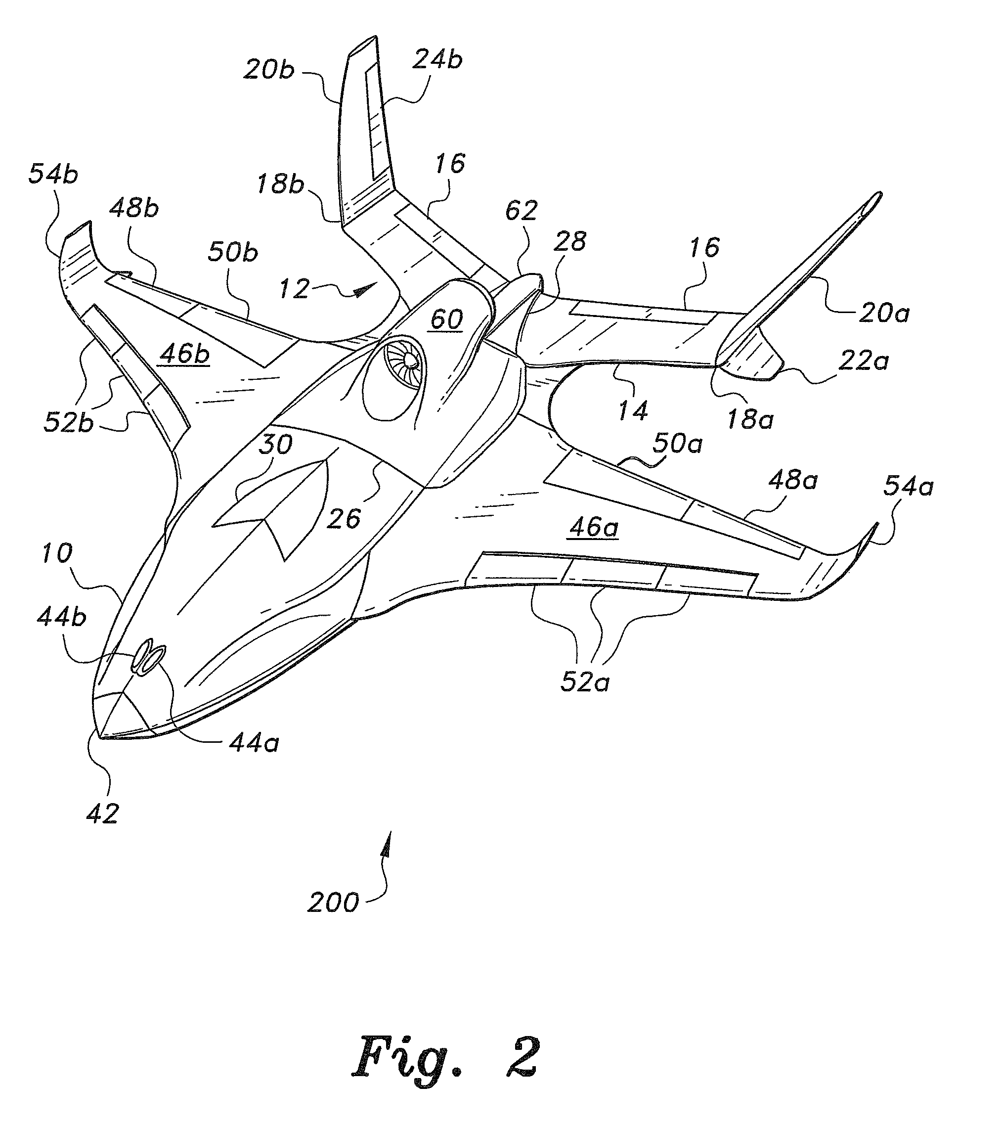
[0046]The fuselage 10 further includes retractable tricycle landing gear, as evidenced by the left main, right main, and nosewheel landing gear doors, respectively 32, 34, and 36, shown in the bottom plan view of the second embodiment modular aircraft 200 of FIG. 18. FIG. 18 also shows the payload bay doors 38 for the internal payload bay 40, shown in broken lines. A radome 42 on the nose of the fuselage 10 protects a radar system installed therebehind. The radome is connected to the fuselage via a rail link mechanism and can be easily replaced. The radar may be any of various types, e.g., weather, targeting, etc., and the various radar units may be interchangeably installed in the fuselage 10. Sensors 44a and 44b are also provided in the nose of the fuselage 10. The sensors may operate in the visual spectrum, or in the infrared or other spectrum. Dual sensors 44a, 44b, along with sensors in the bottom of the fuselage, operate in the visual spectrum to provide a remote operator or p...

first embodiment

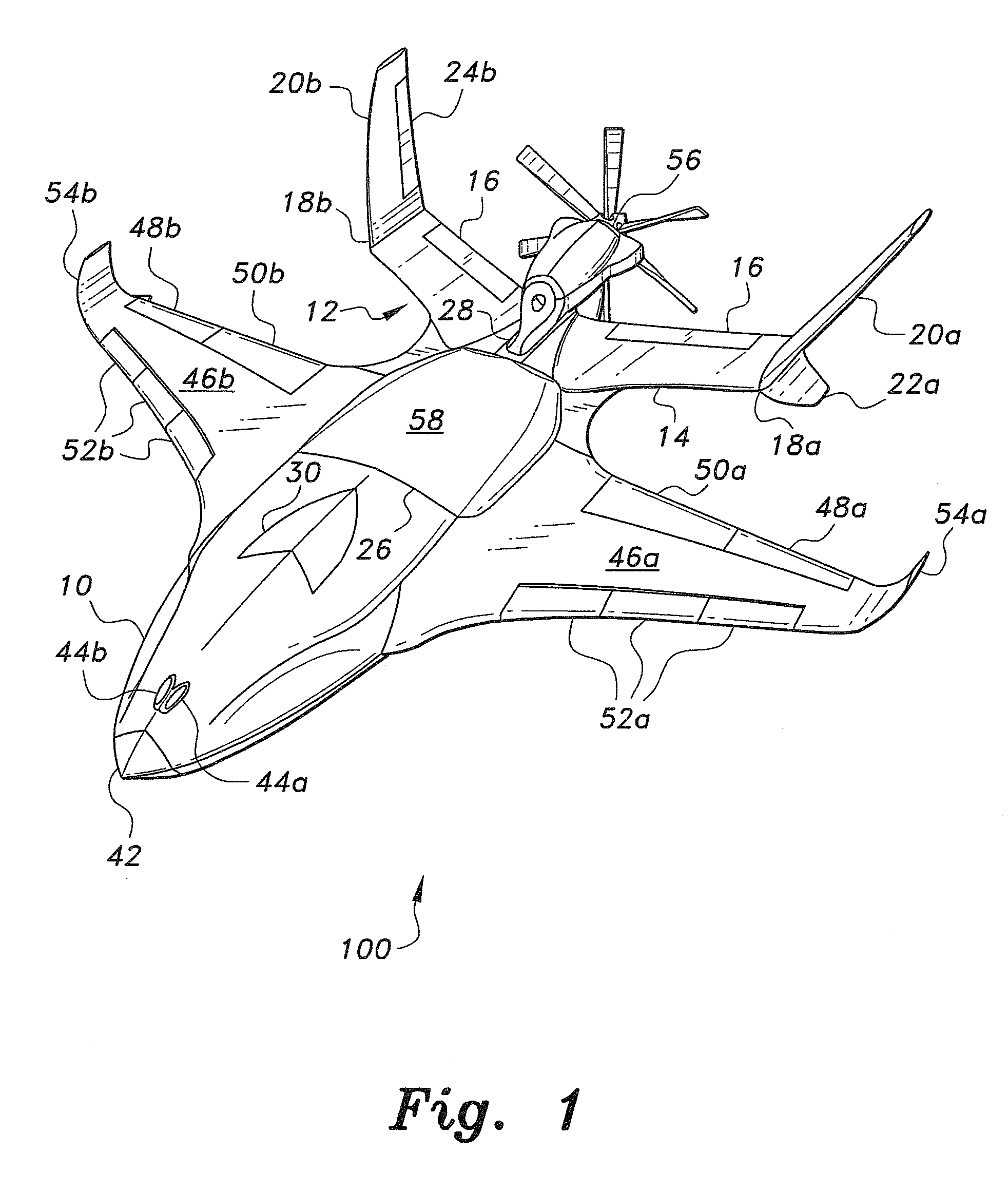
[0048]FIG. 1 provides a perspective view of a first embodiment modular aircraft 100. The fuselage 10 of the modular aircraft 100 is equipped with a short wing module comprising a short left wing 46a and opposite short right wing 46b, the two wings 46a and 46b being essentially in mirror image to one another. Each wing 46a, 46b includes an aileron, respectively 48a and 48b, for roll control, and a flap, respectively 50a and 50b, for additional lift and drag when required. Leading edge slats, respectively 52a and 52b, may also be provided with the wings 46a and 46b of the short wing module. Each wing 46a, 46b is equipped with a blended winglet, respectively 54a and 54b, to reduce aerodynamic losses at the wingtips. The wings 46a, 46b may also be provided with hard points for removable external attachment of weaponry, fuel tanks, etc., as shown schematically in FIGS. 19 and 20 and described further below in the discussion of the systems disclosed in FIGS. 19 and 20.

[0049]The short wing...


PUM


Abstract

The modular aircraft system includes a single fuselage having a permanently installed empennage and plural sets of wing modules and engine modules, with each wing and engine module optimized for different flight conditions and missions. The fuselage and each of the modules are configured for rapid removal and installation of the modules to minimize downtime for the aircraft. Short wings having relatively low aspect ratio are provided for relatively high speed flight when great endurance and/or weight carrying capacity are not of great concern. Long wings having high aspect ratio are provided for longer range and endurance flights where speed is not absolutely vital. A medium span wing module is also provided. Turboprop, single turbojet, and dual turbojet engine modules are provided for installation depending upon mission requirements for any given flight. The aircraft is primarily adapted for use as an autonomously operated or remotely operated unmanned aerial vehicle.

Description

BACKGROUND OF THE INVENTION[0001]1. Field of the Invention[0002]The present invention relates generally to the field of aviation, and particularly to a modular aircraft having interchangeable wing and powerplant modules. The aircraft is particularly adapted as a remotely or autonomously controlled unmanned aerial vehicle (UAV).[0003]2. Description of the Related Art[0004]Virtually all aircraft are designed and engineered to optimize their configurations for specific mission requirements. For example, a long range reconnaissance aircraft requires significantly more fuel than would a short range fighter or interceptor aircraft, while speed may not be critical for a reconnaissance aircraft operating at extreme altitudes. This necessitates different wing configurations and may necessitate different engine configurations as well, depending upon the speed, altitude, and duration desired for each mission.[0005]Accordingly, aircraft intended for fighter interceptor missions are generally co...

Claims


Application Information

Patent Timeline
IPC IPC(8): B64C3/38B64C13/20B64C9/32B64D27/02B64C3/34B64D47/08B64C9/00B64C13/00B64D15/00B64D27/20B64D27/14B64D37/00B64C39/02
CPCB64C3/38B64C13/00B64C9/00B64C13/20B64C9/326B64D27/02B64C3/34B64D47/08B64D15/00B64C39/024B64D37/00B64D27/14B64D27/20B64C2201/063B64C2211/00B64C2201/048B64C2201/141B64C2201/146B64C2201/021B64C2201/16B64C5/06B64D39/00Y02T50/30B64U50/12B64U10/25B64U2201/10B64U2201/20B64U20/40B64U30/14B64U30/40B64U50/14B64U2101/30B64C1/26B64U30/10B64U50/00B64U50/13B64U50/34B64U2101/00
Inventor AL-SABAH, NASSER M.
Owner AL SABAH NASSER M
Why Eureka
Try Eureka