Eureka AIR delivers breakthrough ideas for toughest innovation challenges, trusted by R&D personnel around the world.

Damper device and starting device

Active Publication Date: 2016-07-21
AISIN AW CO LTD
View PDF3 Cites 13 Cited by
  • Summary
  • Abstract
  • Description
  • Claims
  • Application Information

AI Technical Summary

Benefits of technology

This patent aims to improve vibration damping performance by expanding and contracting elastic bodies in a dynamic damper and a damper device that includes the dynamic damper while keeping the device compact. The invention also involves arranging multiple pendulum mass bodies around the elastic bodies to further improve the vibration damping performance of a centrifugal-pendulum vibration absorbing device. In summary, the invention allows for better damping of vivacations in a compact device while utilizing both the dynamic damper and the centrifugal-pendulum vibration absorbing device.

Problems solved by technology

If the third elastic body which constitutes the dynamic damper is disposed at a different position, in the radial direction, from the first and second elastic bodies which transfer torque between the input element and the output element as in the damper device described in Patent Document 1, however, the outside diameter of the damper device may be increased, which makes it difficult to make the entire device compact.
Therefore, the second and third springs may not be adequately expanded and contracted along the axes, and vibration may not be damped well.

Method used


Image

  • Damper device and starting device
  • Damper device and starting device
  • Damper device and starting device

Examples


Embodiment Construction

[0033]Now, an exemplary embodiment will be described with reference to the drawings.

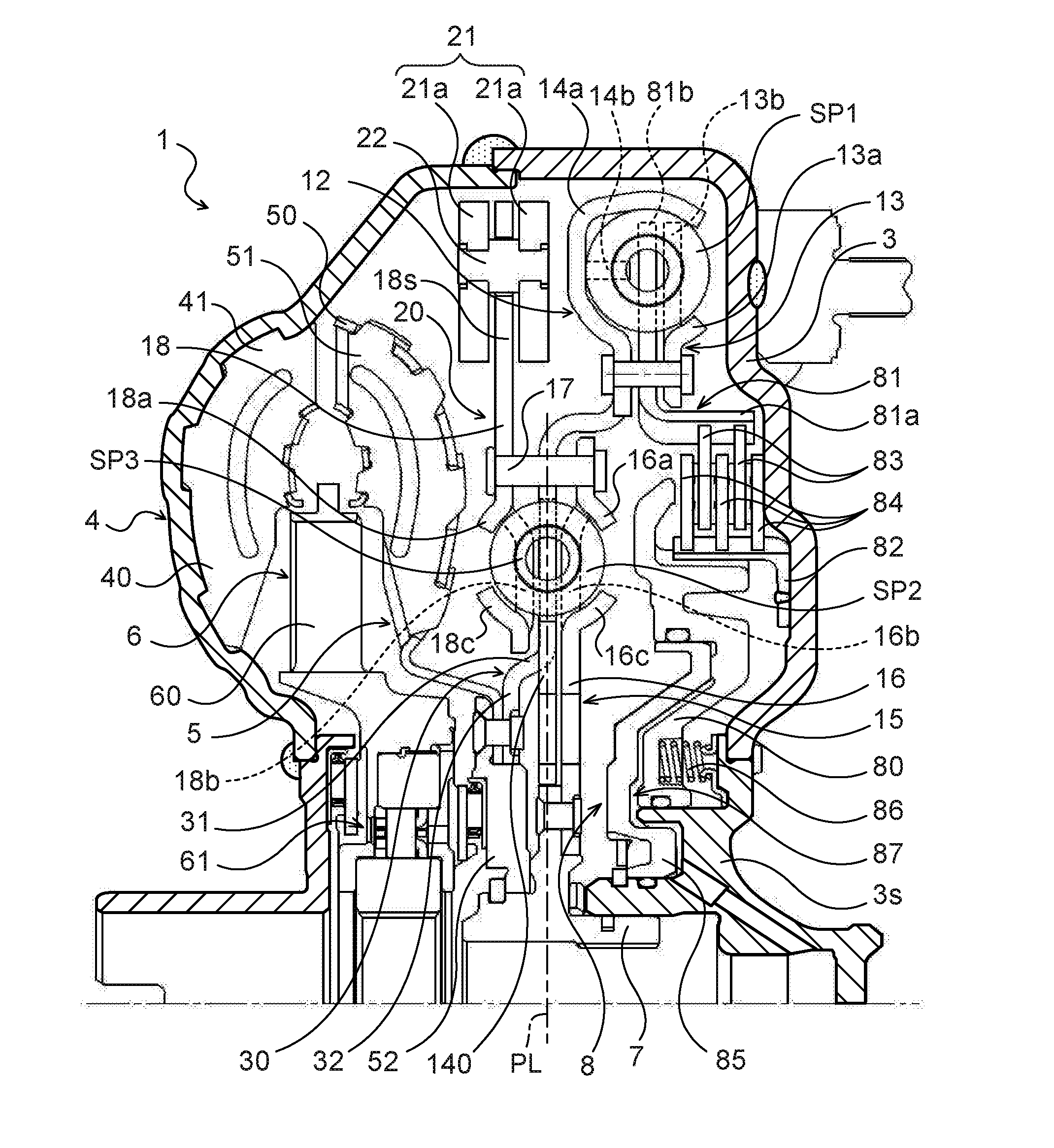
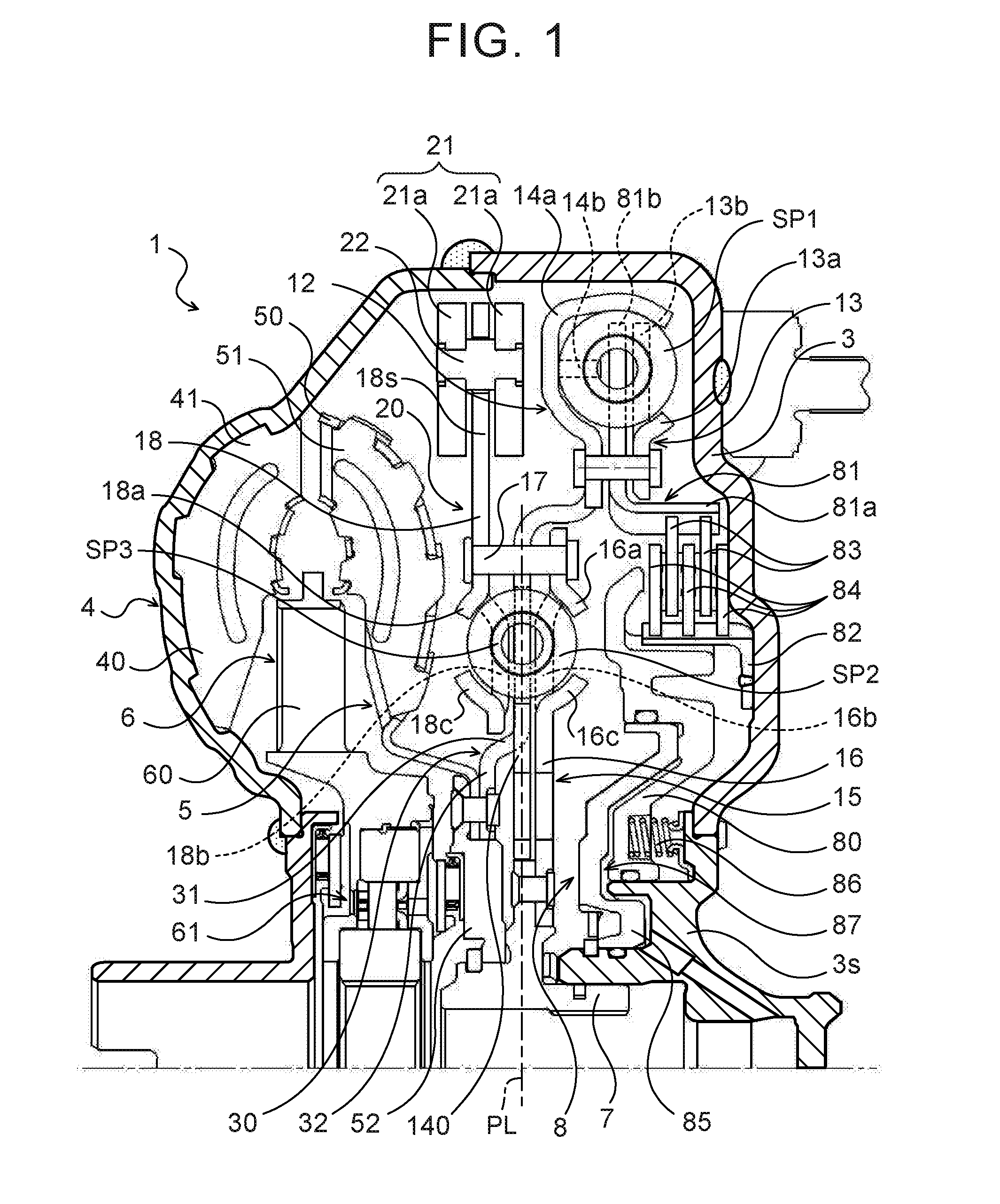
[0034]FIG. 1 is a partial sectional view illustrating a starting device 1 that includes a damper device 10 according to an exemplary embodiment. The starting device 1 illustrated in the drawing is mounted on a vehicle that includes an engine (internal combustion engine) that serves as a motor. In addition to the damper device 10, the starting device 1 includes: a front cover 3 that serves as an input member coupled to a crankshaft of the engine; a pump impeller (input-side fluid transmission element) 4 fixed to the front cover 3; a turbine runner (output-side fluid transmission element) 5 that is coaxially rotatable with the pump impeller 4; a damper hub 7 that serves as an output member coupled to the damper device 10 and fixed to an input shaft IS of a transmission that is an automatic transmission (AT) or a continuously variable transmission (CVT); a lock-up clutch 8 which is a multi-plate hydraul...


PUM


Abstract

An intermediate member of a damper device includes a plate portion that has spring abutment portions that abut against inner springs. Spring abutment portions of a coupling member of a dynamic damper extend from a fixed portion via a bent portion to be disposed in opening portions of the plate portion, and abut against end portions of third springs disposed in the opening portions such that the third springs are arranged side by side with the inner springs in the circumferential direction. The plate portion and the spring abutment portions at least partially overlap each other in the thickness direction. The axes of the inner springs and the third springs are included within the range of overlap between the plate portion and the spring abutment portions in the thickness direction.

Description

TECHNICAL FIELD[0001]The present disclosure relates to a damper device that includes an input element, an output element, a first elastic body that transfers torque between the input element and the output element, and a second elastic body disposed at a position on the inner side of the first elastic body to transfer torque between the input element and the output element, and to a starting device that includes the damper device.BACKGROUND ART[0002]There has hitherto been known a damper device that includes a dynamic damper that has a third elastic body coupled to any rotary element that constitutes the damper device and a mass body coupled to the third elastic body (see Patent Document 1, for example). In the damper device, the third elastic body which constitutes the dynamic damper is disposed on the outer side or the inner side, in the radial direction, of the first and second elastic bodies which transfer torque between the input element and the output element, or between the f...

Claims


Application Information

Patent Timeline
IPC IPC(8): F16F15/134F16H45/02F16D3/12
CPCF16F15/13469F16D3/12F16H2045/0263F16H45/02F16H2045/0226F16F15/134F16H2045/021F16H2045/0284F16F15/12366F16F15/145
Inventor TAKIKAWA, YOSHIHIROOI, YOICHIMIYAOKA, TAKAYUKIHIRAI, YUICHIROYAMAGUCHI, MAKOTOYOSHIKAWA, TAKUYAHATA, MASAHIRO
Owner AISIN AW CO LTD
Why Eureka
Eureka Blog
Learn More