
System and method for z-shim compensated echo-planar magnetic resonance imaging

a magnetic resonance imaging and z-shim technology, applied in the field of medical imaging, can solve the problems of reducing the temporal resolution by half, fmri imaging of the brain acquired using gradient-echo echo-planar imaging (ge-epi) consistently suffers adverse effects, and both geometric distortion and signal loss

Active Publication Date: 2016-07-21
WEILL CORNELL MEDICINE +1
View PDF3 Cites 9 Cited by
  • Summary
  • Abstract
  • Description
  • Claims
  • Application Information

AI Technical Summary

Benefits of technology

The present invention provides a system and method for compensating for magnetic susceptibility variations within a subject to be imaged using a magnetic resonance imaging (MRI) system. The method includes performing a first pulse sequence to select desired shimming parameters, reconstructing a plurality of calibration images, and comparing the calibration images to a comparison image to determine a value of the shimming gradient blips to be included in the desired shimming parameters. The MRI system then performs a second pulse sequence to acquire clinical image data from the subject and reconstruct the clinical image data to form a plurality of clinical composite images. The technical effect of the invention is to improve the accuracy and quality of MRI images by compensating for magnetic susceptibility variations.

Problems solved by technology

Unfortunately, fMRI imaging of the brain acquired using gradient-echo echo-planar imaging (GE-EPI) consistently suffers adverse effects from magnetic field inhomogeneity in regions close to nasal sinuses and ear canals.
The presence of both air and tissue causes magnetic susceptibility variation at the boundary of the two regions, resulting in both geometric distortion and signal loss.
However, doing so necessarily reduces the temporal resolution by half.
However, these methods commonly require longer EPI echo-trains, which can increase susceptibility effects resulting in increased geometric distortion.

Method used


Image

  • System and method for z-shim compensated echo-planar magnetic resonance imaging
  • System and method for z-shim compensated echo-planar magnetic resonance imaging
  • System and method for z-shim compensated echo-planar magnetic resonance imaging

Examples


Embodiment Construction

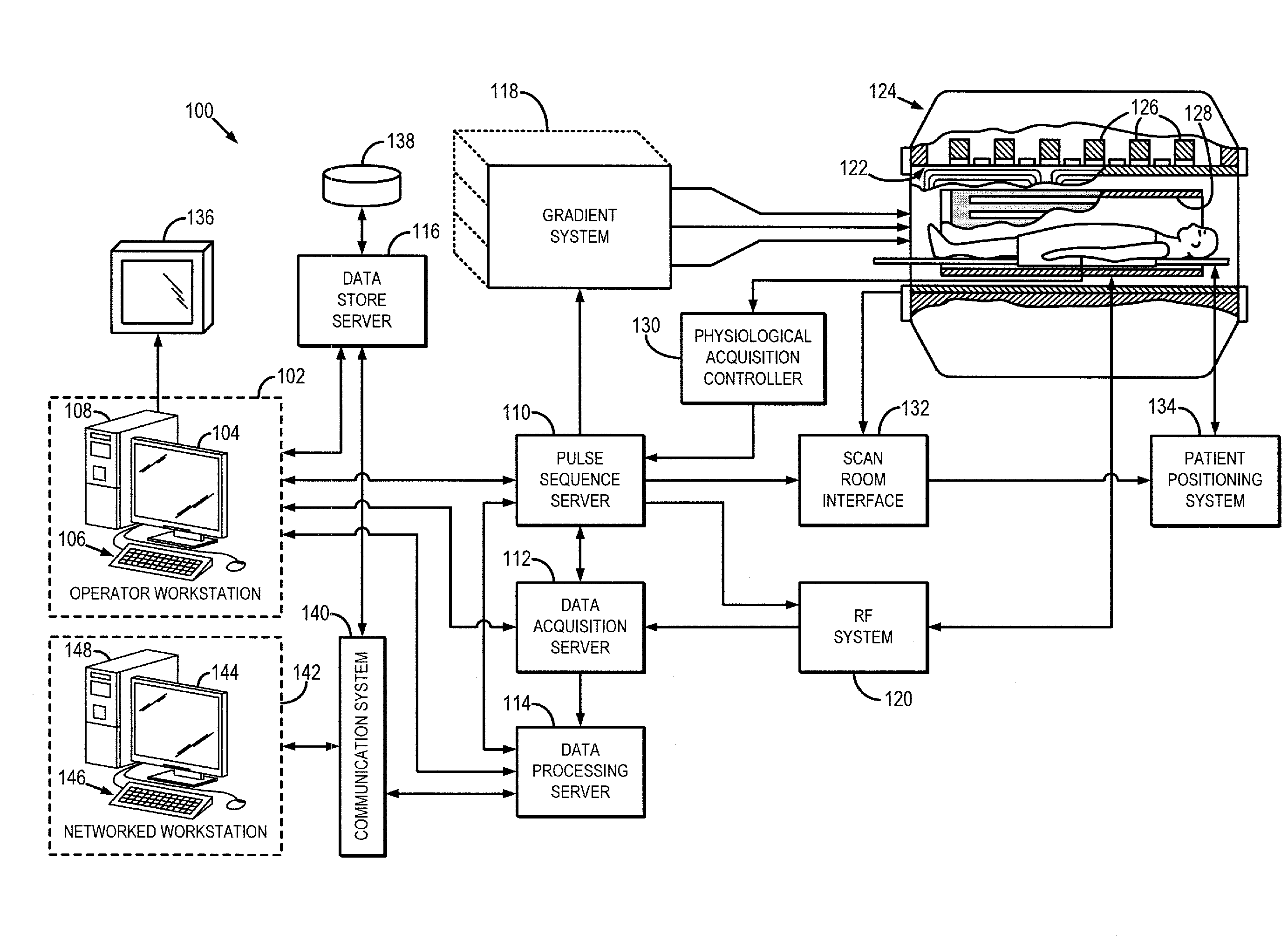
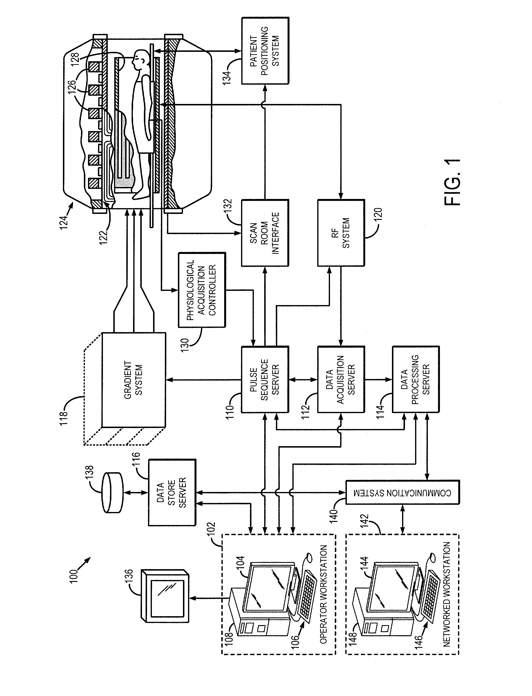
[0019]Referring particularly to FIG. 1, an example of a magnetic resonance imaging (MRI) system 100 is illustrated. The MRI system 100 includes a workstation 102 having a display 104 and a keyboard 106. The workstation 102 includes a processor 108 that is commercially available to run a commercially-available operating system. The workstation 102 provides the operator interface that enables scan prescriptions to be entered into the MRI system 100. The workstation 102 is coupled to four servers: a pulse sequence server 110; a data acquisition server 112; a data processing server 114; and a data store server 116. The workstation 102 and each server 110, 112, 114, and 116 are connected to communicate with each other.

[0020]The pulse sequence server 110 functions in response to instructions downloaded from the workstation 102 to operate a gradient system 118 and a radiofrequency (RF) system 120. Gradient waveforms necessary to perform the prescribed scan are produced and applied to the g...


PUM


Abstract

A system and method for imaging a subject includes a first imaging pulse sequence having gradient blips along an x-direction and a y-direction to acquire calibration image data from multiple slices. The imaging pulse sequence also includes a plurality of Z-shimming gradient blips coincident in time with the gradient blips along the x- and y-directions and varied within each slice. A plurality of calibration images are reconstructed from the calibration image data and a comparison image is formed by selecting an image from the calibration images corresponding to at least one of the varied Z-shimming gradient blips for each slice to determine a desired value of the Z-shimming gradient blips. The desired values are used to perform a second pulse sequence to acquire clinical image data from the subject. The second pulse sequence is used to acquire clinical images having been compensated for magnetic susceptibility variations within the subject.

Description

CROSS REFERENCE[0001]This application is based on, claims priority to, and incorporates herein by reference in its entirety, U.S. Provisional Patent Application Ser. No. 61 / 871,103, filed Aug. 28, 2013, and entitled “SYSTEM AND METHOD FOR Z-SHIM COMPENSATED ECHO-PLANAR MAGNETIC RESONANCE IMAGING.”BACKGROUND OF THE INVENTION[0002]The present disclosure relates to medical imaging. More particularly, the disclosure relates to Z-shim compensation for magnetic resonance imaging (MRI).[0003]When a substance such as human tissue is subjected to a uniform magnetic field (polarizing field B0) applied along, for example, a Z axis of a Cartesian coordinate system, the individual magnetic moments of the spins in the tissue attempt to align with this polarizing field, but precess about it in random order at their characteristic Larmor frequency. If the substance, or tissue, is subjected to a magnetic field (excitation field B1) that is in the x-y plane and that is near the Larmor frequency, the ...

Claims


Application Information

Patent Timeline
Patent Type & Authority Applications(United States)
IPC IPC(8): G01R33/565G01R33/48G01R33/561
CPCG01R33/56536G01R33/4806G01R33/5616G01R33/4835
Inventor STERN, EMILYSILBERSWEIG, DAVIDPAN, HONG
Owner WEILL CORNELL MEDICINE
Learn More