Silicon carbide semiconductor device and method of manufacturing the same
a technology of silicon carbide and semiconductor devices, applied in the direction of semiconductor devices, basic electric elements, electrical equipment, etc., to achieve the effect of simplified construction and high current gain
- Summary
- Abstract
- Description
- Claims
- Application Information
AI Technical Summary
Benefits of technology
Problems solved by technology
Method used
Image
Examples
first embodiment
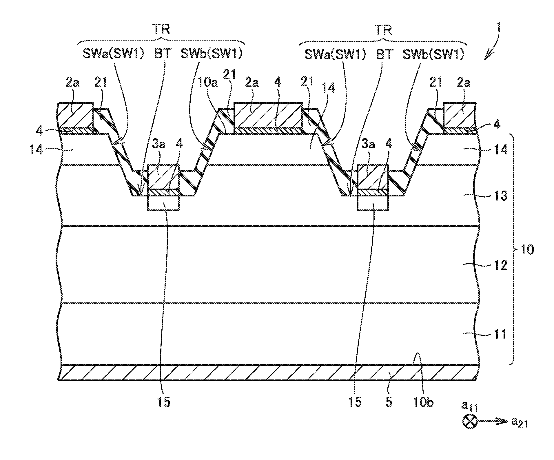
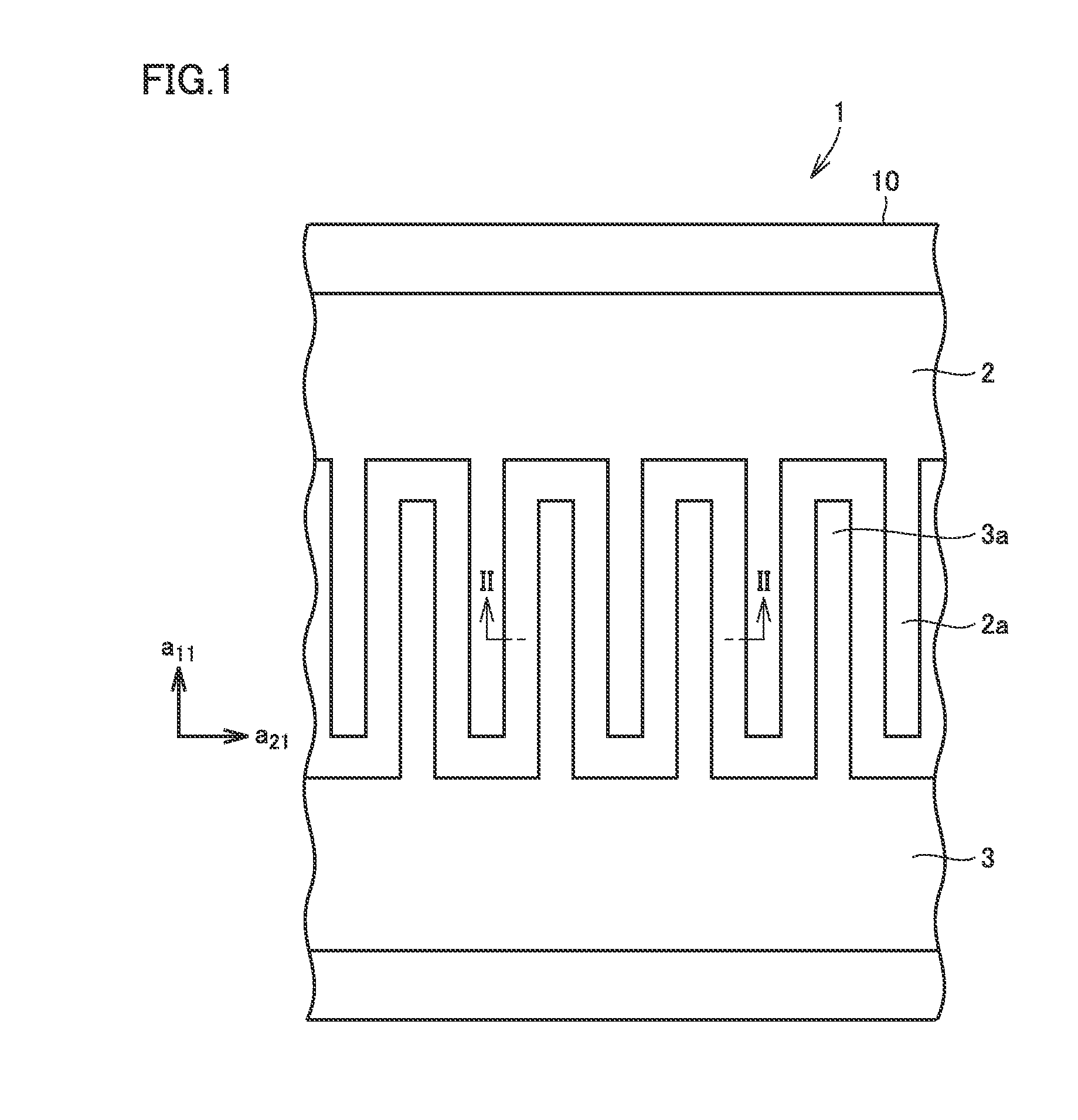
[0079]FIG. 1 is a plan view showing a schematic construction of a silicon carbide semiconductor device according to a first embodiment of the present invention. FIG. 2 is a cross-sectional view along the line II-II in FIG. 1.
[0080]Referring to FIGS. 1 and 2, a silicon carbide semiconductor device 1 according to the first embodiment is a bipolar transistor. More specifically, silicon carbide semiconductor device 1 according to the first embodiment is an npn bipolar transistor.
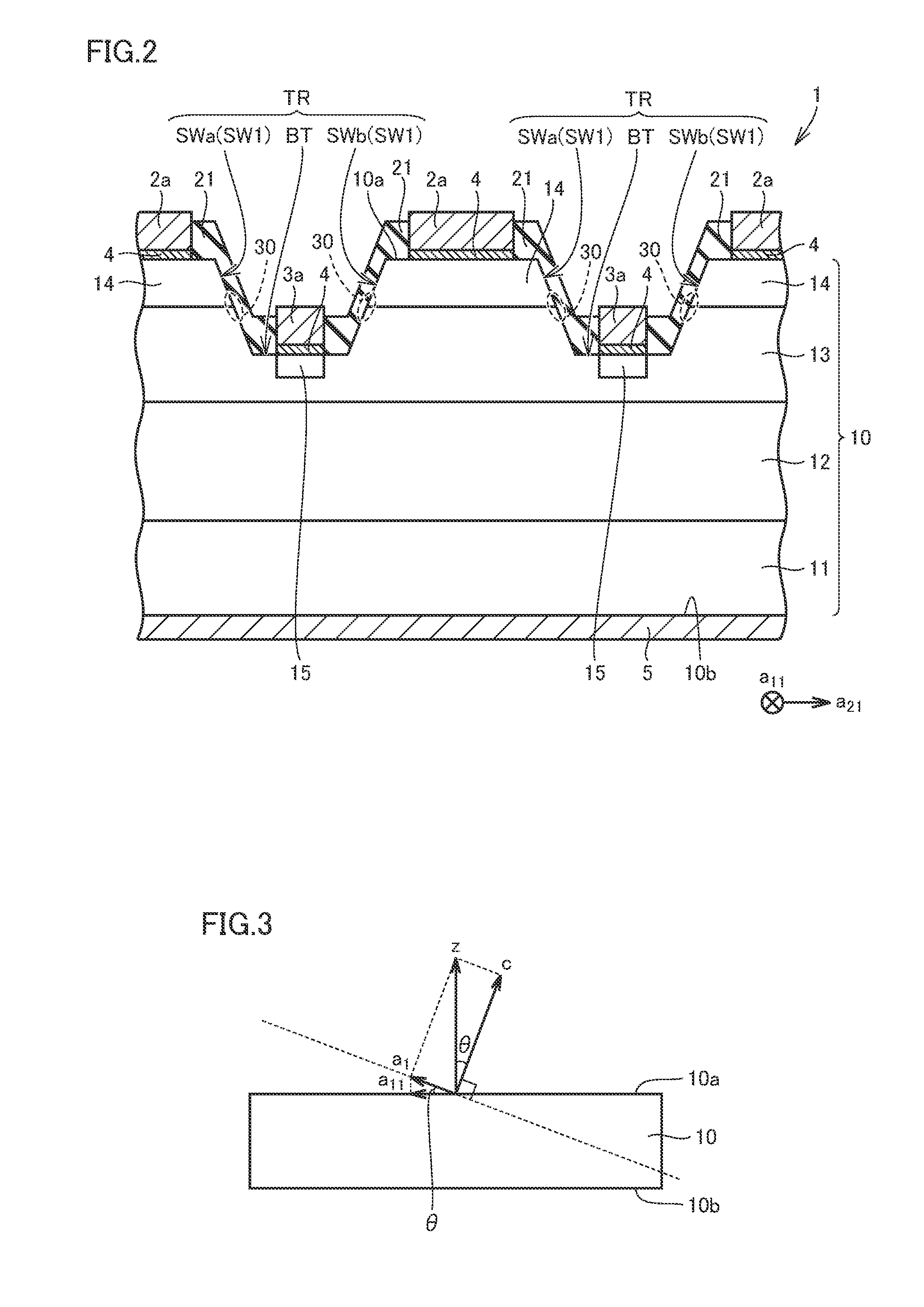
[0081]Silicon carbide semiconductor device 1 includes a silicon carbide layer 10, an insulating film 21, an emitter electrode 2a, a base electrode 3a, an ohmic electrode 4, and a collector electrode 5. As shown in FIG. 1, in a plan view, emitter electrode 2a and base electrode 3a extend along a direction shown with a11 and alternately aligned along a direction shown with a21. Direction all and direction a21 are directions orthogonal to each other. Direction all and direction a21 will be described in detail later...
second embodiment
[0134]FIG. 15 is a plan view showing a schematic construction of a silicon carbide semiconductor device according to a second embodiment of the present invention. FIG. 16 is a cross-sectional view along the line XVI-XVI in FIG. 15.
[0135]Referring to FIGS. 15 and 16, a silicon carbide semiconductor device 1A according to the second embodiment is different from silicon carbide semiconductor device 1 according to the first embodiment in a cross-sectional shape of trench TR.
[0136]Each of sidewall surfaces SWa and SWb includes first region SW1 and a second region SW2. First region SW1 is a region including a special surface. Second region SW2 is a region having a depth from first main surface 10a of silicon carbide layer 10 to a position shallower than a junction surface between n+ type layer 14 (emitter region) and p-type layer 13 (base region). Furthermore, second region SW2 continues to first region SW1.
[0137]An angle θ1 is an angle formed by first region SW1 with respect to first mai...
third embodiment
[0143]FIG. 20 is a plan view showing a schematic construction of a silicon carbide semiconductor device according to a third embodiment of the present invention. FIG. 21 is a cross-sectional view along the line XXI-XXI in FIG. 20.
[0144]Referring to FIGS. 20 and 21, a silicon carbide semiconductor device 1B according to the third embodiment is different from silicon carbide semiconductor device 1 according to the first embodiment and silicon carbide semiconductor device 1A according to the second embodiment in cross-sectional shape of trench TR.
[0145]More specifically, each of sidewall surfaces SWa and SWb includes first region SW1 and second region SW2. First region SW1 is a region including a special surface. Second region SW2 is a region continuing from first main surface 10a of silicon carbide layer 10 through n+ type layer 14 (emitter region) to first region SW1.
[0146]As in the second embodiment, angle θ1 is an angle formed by first region SW1 with respect to first main surface ...
PUM
| Property | Measurement | Unit |
|---|---|---|
| angle | aaaaa | aaaaa |
| angle | aaaaa | aaaaa |
| total azimuth angle | aaaaa | aaaaa |
Abstract
Description
Claims
Application Information
 - R&D
- Intellectual Property
- Life Sciences
- Materials
- Tech Scout
- Unparalleled Data Quality
- Higher Quality Content
- 60% Fewer Hallucinations
Browse by: Latest US Patents, China's latest patents, Technical Efficacy Thesaurus, Application Domain, Technology Topic, Popular Technical Reports.
© 2025 PatSnap. All rights reserved.Legal|Privacy policy|Modern Slavery Act Transparency Statement|Sitemap|About US| Contact US: help@patsnap.com


