
Voltage surge protection for active rectifiers in the event of load shedding

a technology of voltage surge protection and active rectifiers, which is applied in the direction of generator control by field variation, electric devices, transportation and packaging, etc., can solve problems such as not always achieved, and achieve the effect of low cos

Active Publication Date: 2016-07-21
SEG AUTOMOTIVE GERMANY GMBH
View PDF2 Cites 9 Cited by
  • Summary
  • Abstract
  • Description
  • Claims
  • Application Information

AI Technical Summary

Benefits of technology

The patent text describes a method for controlling the output voltage of a generator using half-bridges. Due to tolerances in the control circuit, one half-bridge may conduct at a higher voltage than the others. This higher threshold results in the control circuit being constantly in a conductive state, regardless of the other half-bridges. The generator controller uses a generator setpoint voltage to keep the voltage constant, regardless of changes in speed and load. The output voltage is used as the actual value. This method can improve battery charge and prevent overcharging. The software implementation is cost-effective and can be downloaded via computer networks.

Problems solved by technology

In the mentioned, decentralized active bridge rectifiers, in which the individual half-bridges each include independent control circuits, which each individually detect the output voltage applied to the DC voltage terminals of the active bridge rectifier, such operation is also sought, but is not always achieved in the related art due to the above-explained tolerances in the voltage recognition and / or in downstream elements of the control circuits.

Method used


Image

  • Voltage surge protection for active rectifiers in the event of load shedding
  • Voltage surge protection for active rectifiers in the event of load shedding
  • Voltage surge protection for active rectifiers in the event of load shedding

Examples


Embodiment Construction

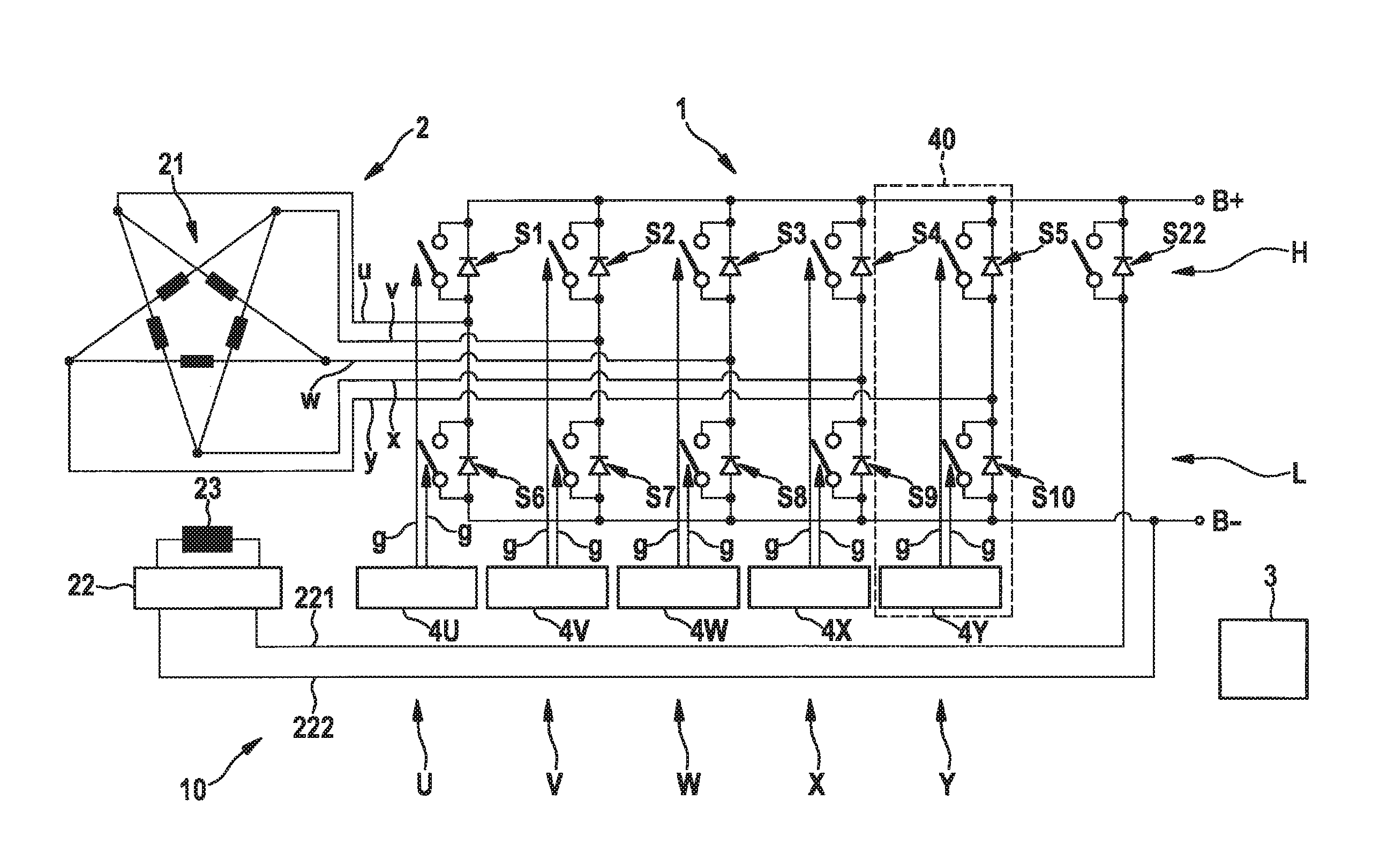
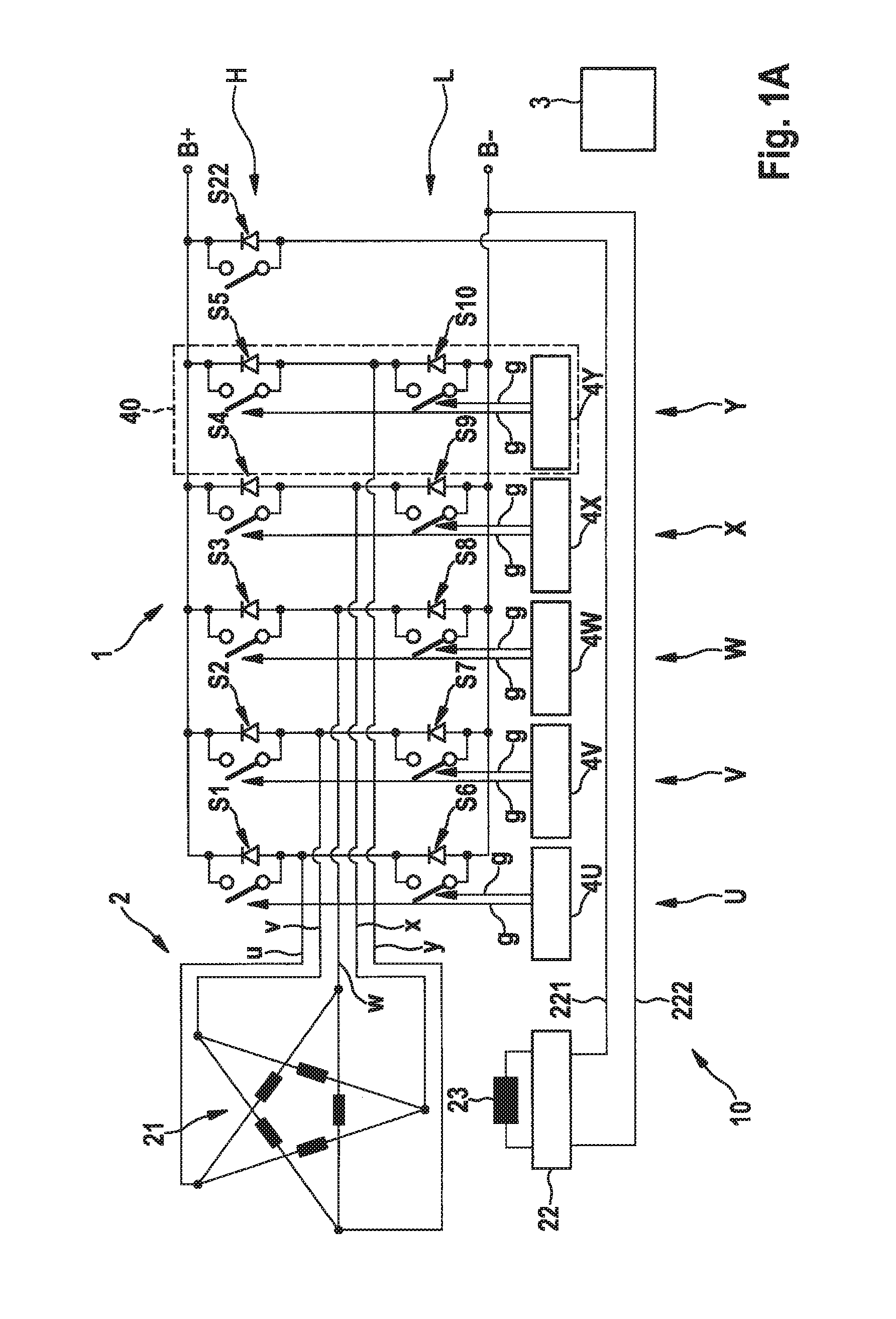
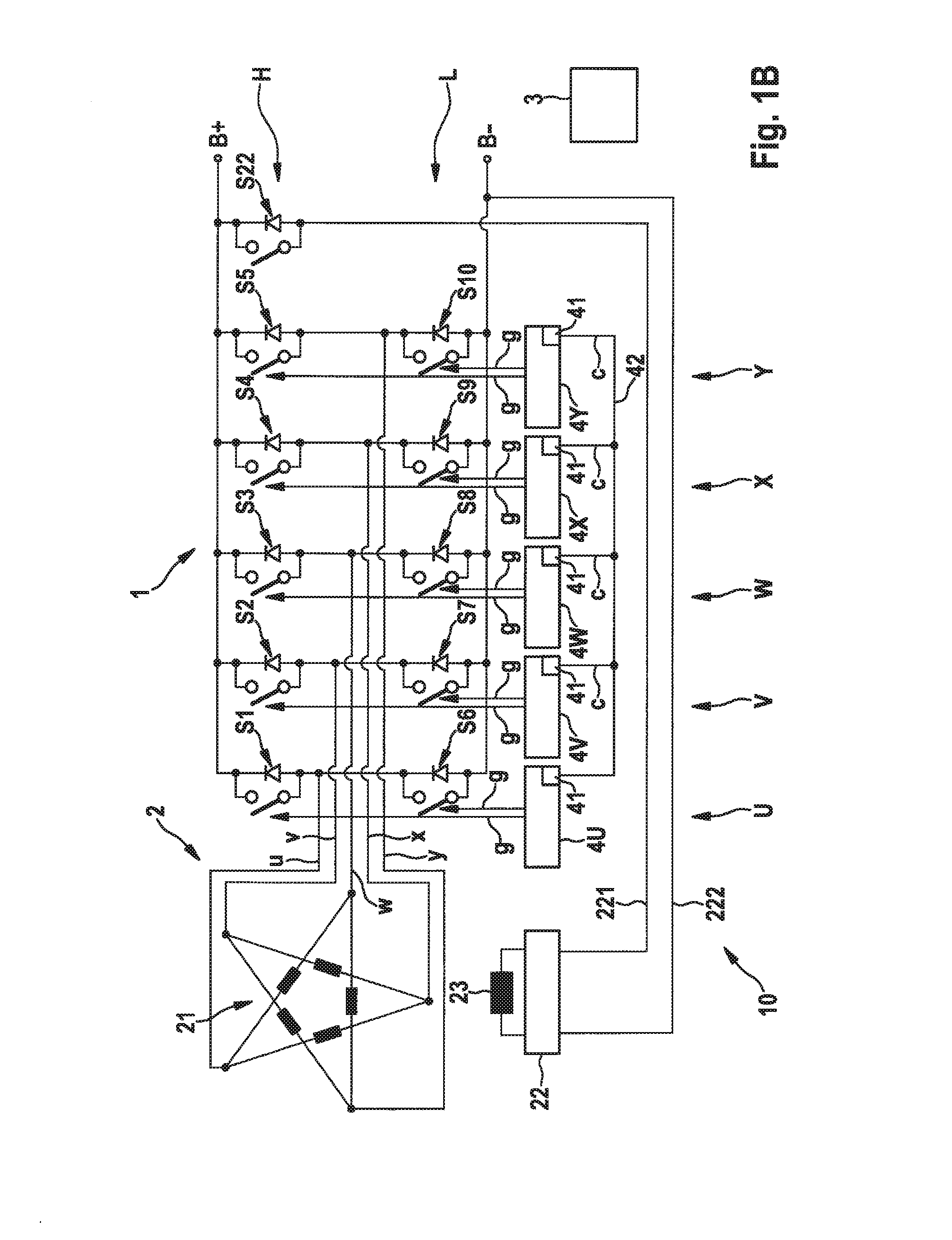
[0070]FIGS. 1A through 1C show generator arrays including active bridge rectifiers and the function thereof in schematic views. The generator arrays are each identified as a whole with reference numeral 10. They each include an active bridge rectifier 1 including five half-bridges U through Y here, for example. The five half-bridges U through Y may each be configured as corresponding rectifier modules, as illustrated here only with respect to rectifier module 40 in FIG. 1A (half-bridge Y) for the sake of clarity. Generator arrays 10 furthermore include a five-phase generator 2 here, for example.

[0071]The five half-bridges U through Y are each incorporated between the two DC voltage terminals B+ and B− of active bridge rectifier 1, each half-bridge U through Y having two activatable switching elements, which are connected in series between the two DC voltage terminals B+ and B−, and are identified here with S1 through S10. Switching elements S1 through S10 are illustrated as switches...


PUM


Abstract

A rectifier module for an active bridge rectifier having two switching elements, connected in series between two end terminals, and between which a center tap is formed, and a control circuit including a monitoring unit, a synchronization unit, and a control unit, the monitoring unit detecting a measuring voltage and outputting a request signal when the measuring voltage exceeds an upper threshold value. The synchronization unit outputs a synchronization signal to a synchronization terminal as long as the monitoring unit outputs the request signal, and otherwise to monitor the synchronization terminal for a synchronization signal. The control unit switches one of the two switching elements into a conductive state at least in sections during an activation period of time, when the monitoring unit outputs the request signal and / or when the synchronization signal is detected and is optionally recognized as valid by the monitoring. Also described is an active bridge rectifier including corresponding rectifier modules, a generator array including such a bridge rectifier, a corresponding motor vehicle electrical system, an operating method, and an arrangement for the method.

Description

FIELD OF THE INVENTION[0001]The present invention relates to a rectifier module for an active bridge rectifier including an arrangement for protection from voltage surges in the event of load shedding, an active bridge rectifier including corresponding rectifier modules, a generator array including such a bridge rectifier, a corresponding motor vehicle electrical system, an associated operating method, and an arrangement for implementing this operating method.BACKGROUND INFORMATION[0002]Rectifiers of different designs may be used for supplying DC systems from AC systems. In motor vehicle electrical systems, bridge rectifiers in a six-pulse version are frequently used in accordance with the three-phase AC generators typically installed therein. The present invention is similarly suitable, however, for bridge rectifiers for other numbers of phases, for example, for four-phase or five-phase generators.[0003]One critical operating condition in the case of bridge rectifiers is load shedd...

Claims


Application Information

Patent Timeline
Patent Type & Authority Applications(United States)
IPC IPC(8): H02M1/32H02P9/14B60R16/03H02M7/219
CPCH02M1/32H02M7/219H02M2001/327B60R16/03H02P9/14H02M1/084H02M7/2173H02P9/006H02P25/22H02P29/0241Y02T10/92H02M1/327
Inventor SCHUELER, HARALDSAUTTER, SIEGBERTOTTE, CHRISTOPHERMEHRINGER, PAULGE, JIEFEILER, WOLFGANGSCHMIDT, MATTHIAS
Owner SEG AUTOMOTIVE GERMANY GMBH
Learn More