Modular top drive system

a top drive and module technology, applied in the direction of rotary drilling, drilling pipes, drilling/well accessories, etc., can solve the problems of time-consuming and dangerous rig personnel, the threaded connection between the quill and the gripping head also unduly limits the load capacity of the top drive in the casing mod

Active Publication Date: 2016-07-28
WEATHERFORD TECH HLDG LLC
View PDF4 Cites 69 Cited by
  • Summary
  • Abstract
  • Description
  • Claims
  • Application Information

AI Technical Summary

Benefits of technology

[0010]In another embodiment, a method of operating a modular top drive system includes: retrieving a drilling unit from a unit rack; raising the retrieved drilling unit to or above the rig floor; delivering the retrieved drilling unit to a motor unit connected to a rail of the drilling rig; aligning a latch profile of the motor unit with a latch profile of the drilling unit; inserting the drilling unit into the motor unit; and engaging the latch profiles, thereby connecting the drilling unit to the motor unit.

Problems solved by technology

This shifting of the top drive between drilling and casing modes is time consuming and dangerous requiring rig personnel to work at heights.
The threaded connection between the quill and the gripping head also unduly limits the load capacity of the top drive in the casing mode.

Method used


Image

  • Modular top drive system
  • Modular top drive system
  • Modular top drive system

Examples


Embodiment Construction

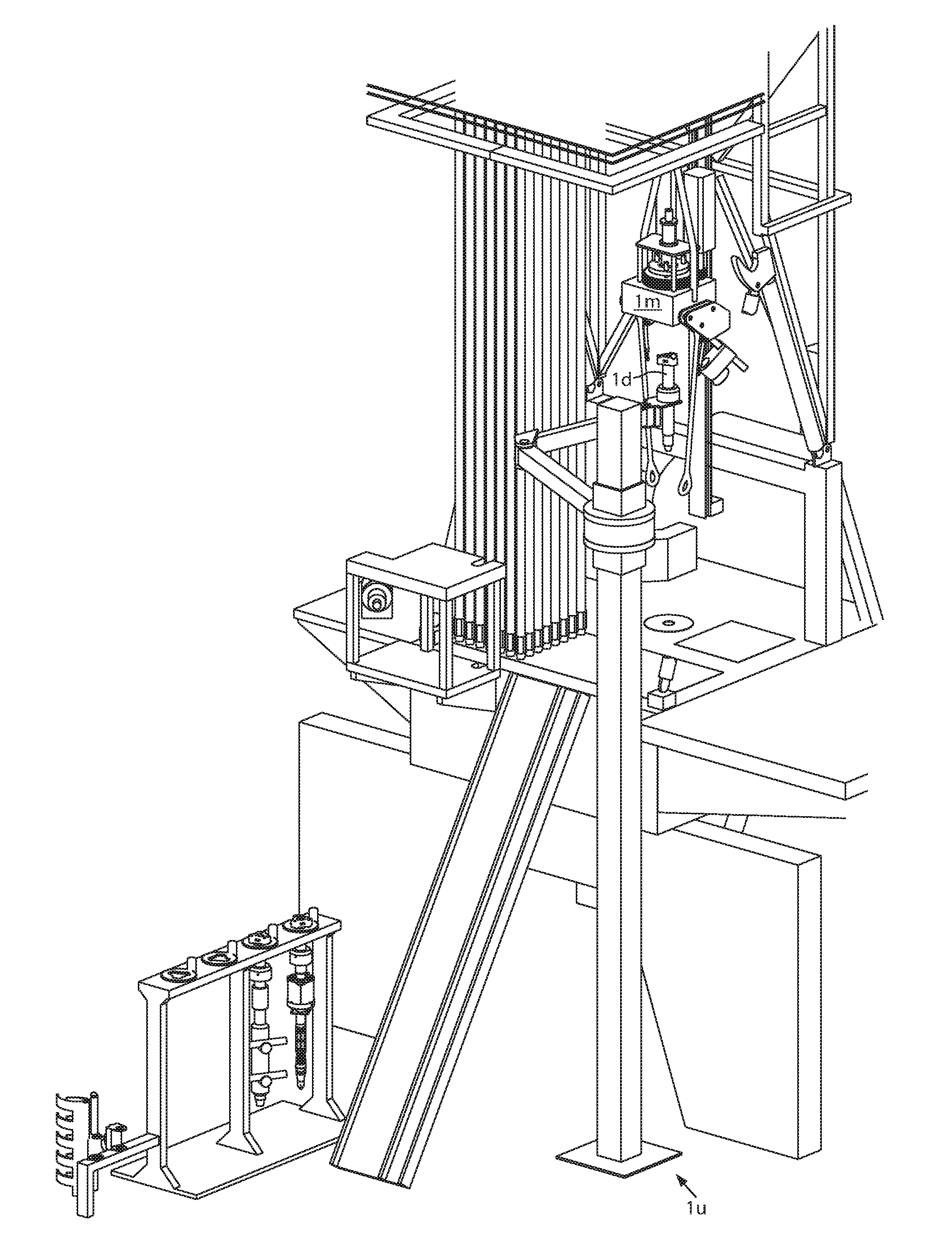
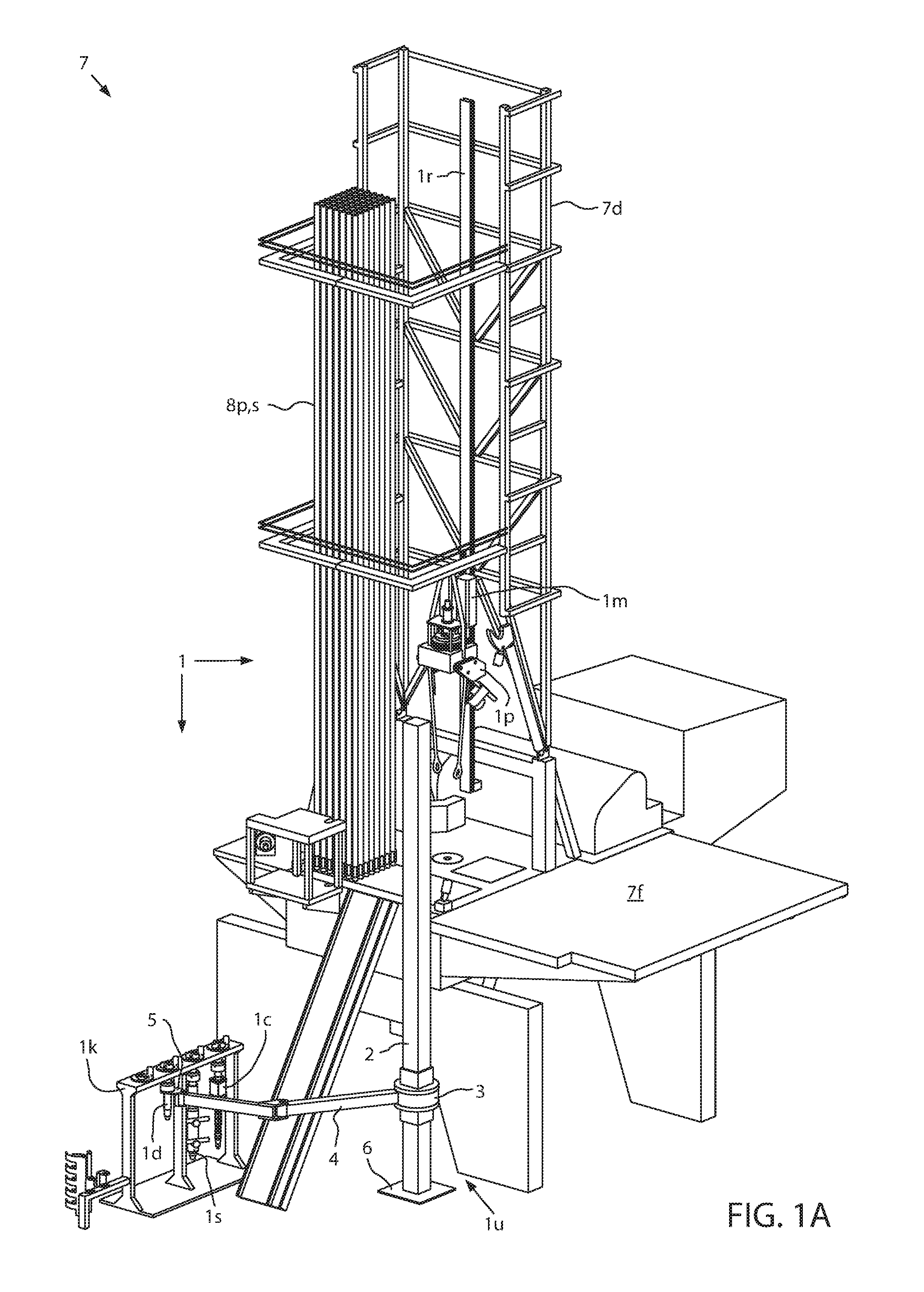
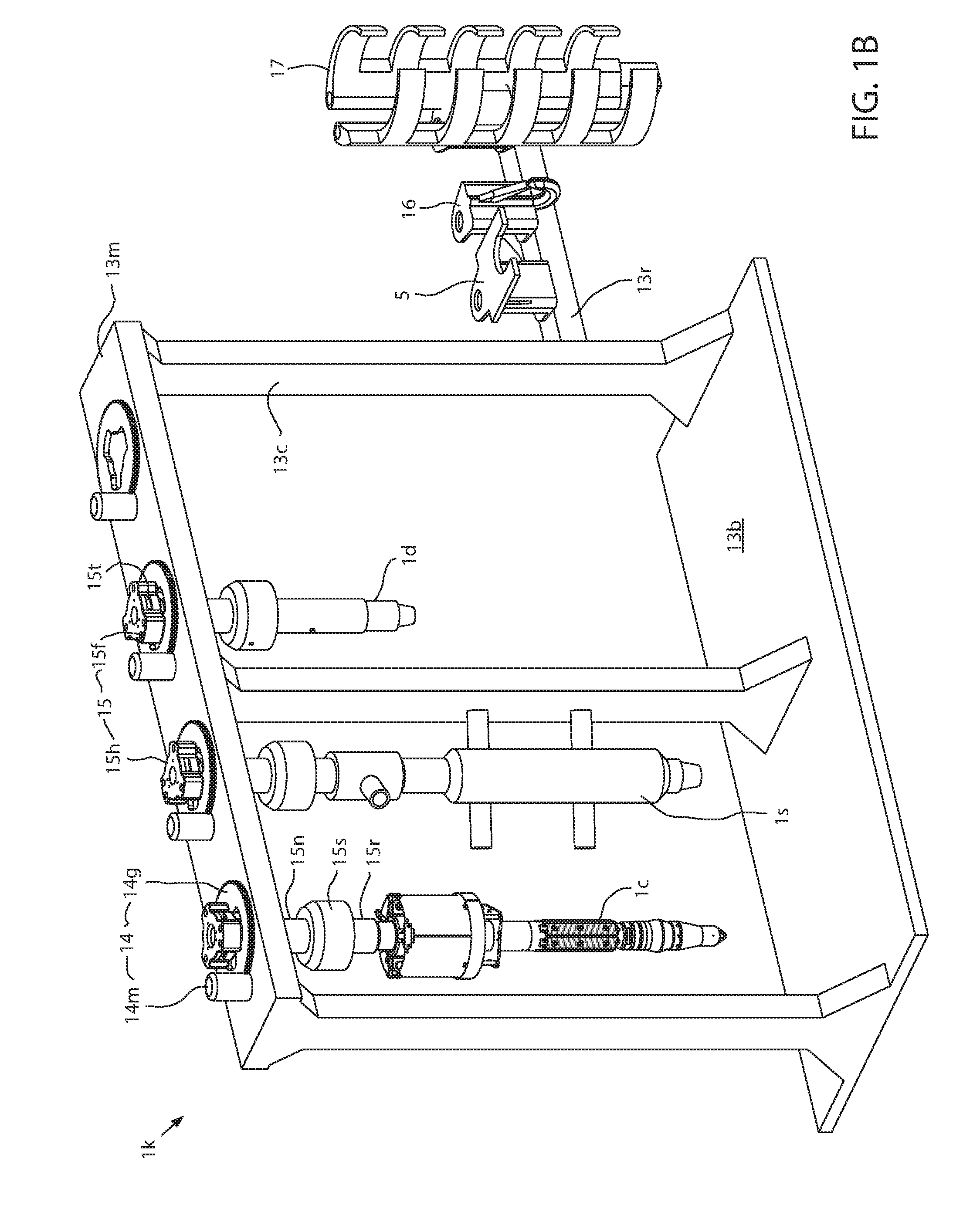
[0025]FIG. 1A illustrates a modular top drive system 1, according to one embodiment of the present disclosure. The modular top drive system 1 may include a linear actuator 1a (FIG. 4L), a casing unit 1c, a drilling unit 1d, a pipe handler 1p, a unit rack 1k, a motor unit 1m, a rail 1r, a cementing unit 1s, and a unit handler 1u. The unit handler 1u may include a post 2, a slide hinge 3, an arm 4, a holder 5, a base 6, and one or more actuators (not shown).

[0026]The modular top drive system 1 may be assembled as part of a drilling rig 7 by connecting a lower end of the rail 1r to a floor 7f of the rig and an upper end of the rail to a derrick 7d of the rig such that a front of the rail is adjacent to a drill string opening in the rig floor. The rail 1r may have a length sufficient for the top drive system 1 to handle stands 8s of two to four joints of drill pipe 8p. It should be noted that the rail 1r may have a length for the top drive system 1 to hand more joints of drill pipe 8p. ...


PUM


Abstract

A modular top drive system for construction of a wellbore includes a motor unit. The motor unit includes: a drive body; a drive motor having a stator connected to the drive body; a trolley for connecting the drive body to a rail of a drilling rig; and a drive ring torsionally connected to a rotor of the drive motor and having a latch profile for selectively connecting one of: a drilling unit, a casing unit, and a cementing unit to the motor unit.

Description

BACKGROUND OF THE DISCLOSURE[0001]1. Field of the Disclosure[0002]The present disclosure generally relates to a modular top drive system.[0003]2. Description of the Related Art[0004]A wellbore is formed to access hydrocarbon-bearing formations (e.g., crude oil and / or natural gas) or for geothermal power generation by the use of drilling. Drilling is accomplished by utilizing a drill bit that is mounted on the end of a drill string. To drill within the wellbore to a predetermined depth, the drill string is often rotated by a top drive on a surface rig. After drilling to a predetermined depth, the drill string and drill bit are removed and a section of casing is lowered into the wellbore. An annulus is thus formed between the string of casing and the formation. The casing string is hung from the wellhead. A cementing operation is then conducted in order to fill the annulus with cement. The casing string is cemented into the wellbore by circulating cement into the annulus defined betwe...

Claims


Application Information

Patent Timeline
Patent Type & Authority Applications(United States)
IPC IPC(8): E21B41/00E21B3/02
CPCE21B3/02E21B41/00E21B19/16E21B3/022
Inventor HELMS, MARTINLIESS, MARTIN
Owner WEATHERFORD TECH HLDG LLC
Why Eureka
Try Eureka