Valve For A Vibration Damper, Vibration Damper, And Motor Vehicle

a technology for dampers and valves, applied in shock absorbers, mechanical equipment, transportation and packaging, etc., can solve the problem that known flow valves cannot be utilized for the targeted application

Active Publication Date: 2016-07-28
ZF FRIEDRICHSHAFEN AG
View PDF12 Cites 2 Cited by
  • Summary
  • Abstract
  • Description
  • Claims
  • Application Information

AI Technical Summary

Benefits of technology

[0009]It is an object of the present application to provide a valve which can be operated in a purely mechanical manner and controlled substantially depending on volum...

Problems solved by technology

But known flow valves cannot be utilized for the targeted application in a vibration damper because they are either ...

Method used


Image

  • Valve For A Vibration Damper, Vibration Damper, And Motor Vehicle
  • Valve For A Vibration Damper, Vibration Damper, And Motor Vehicle
  • Valve For A Vibration Damper, Vibration Damper, And Motor Vehicle

Examples


Embodiment Construction

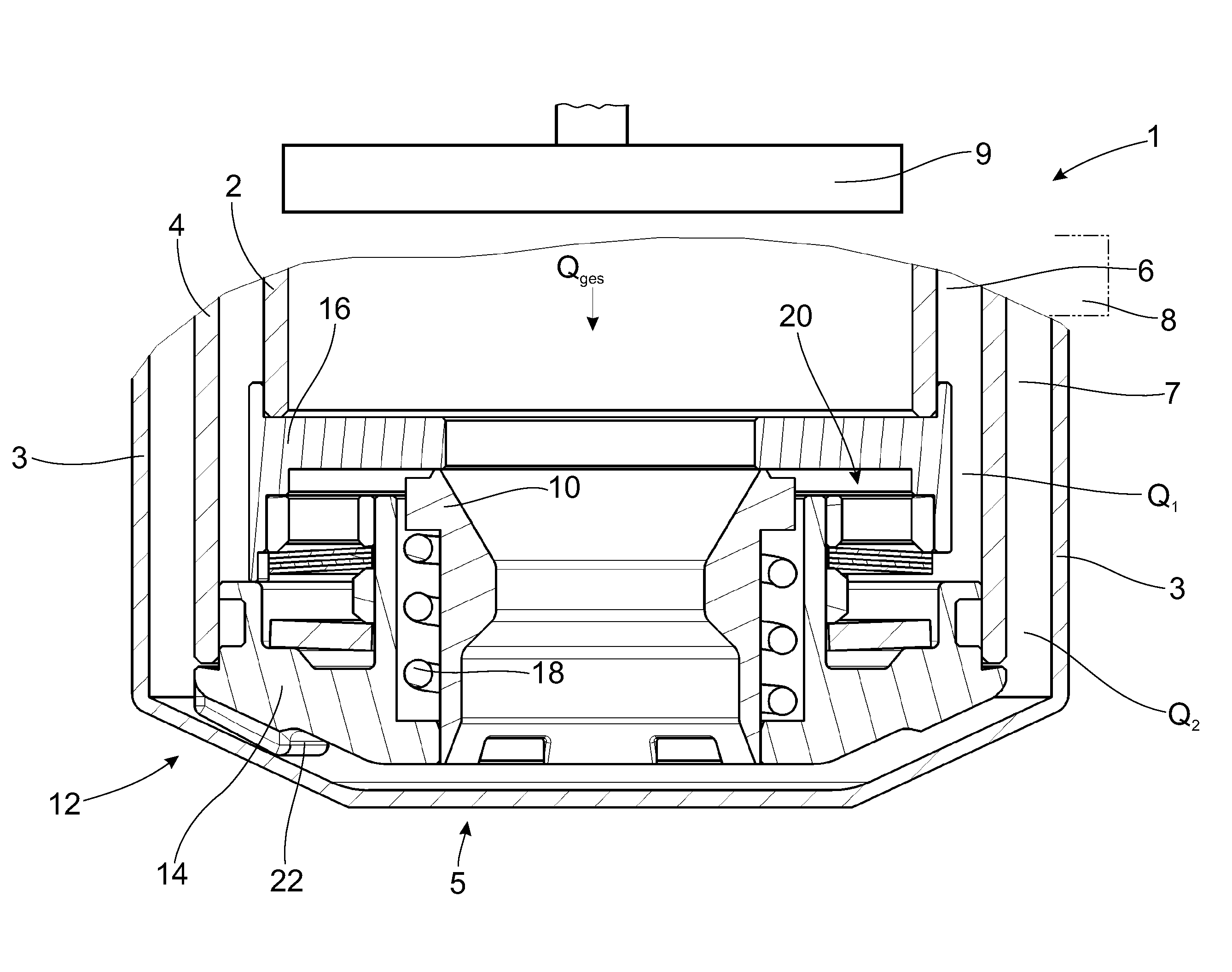
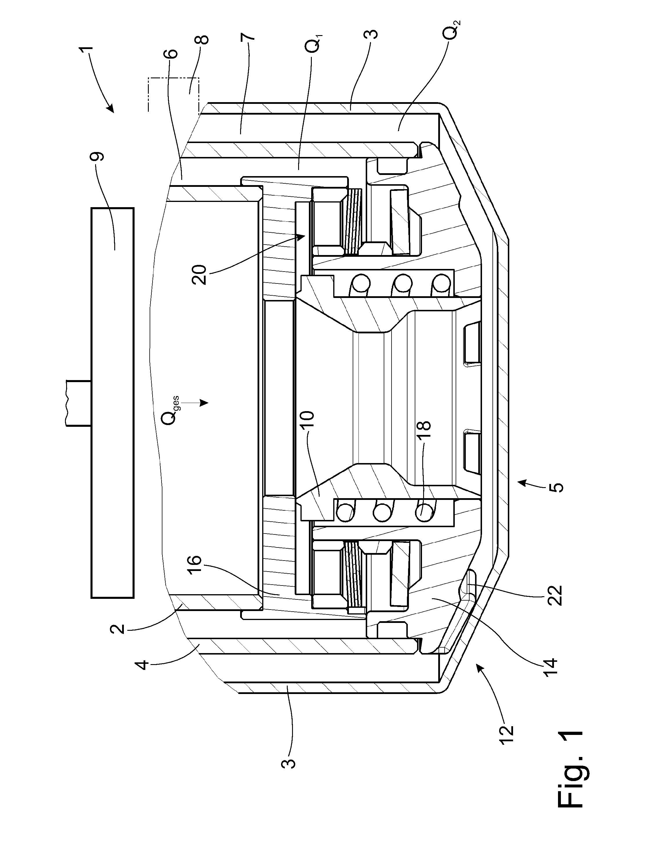
[0043]FIG. 1 shows a portion of a vibration damper 1 with an inner tube element 2, an outer tube element 3, a center tube element 4 arranged between the inner tube element 2 and outer tube element 3, and a valve 5. A bypass path 6 is located between the inner tube element 2 and center tube element 4, and a main flow path 7 is located between the center tube element 4 and outer tube element 3. A damping force generating device, e.g., a damper valve 8, which is to be protected against excessively large volume flows, is located in the main flow path 7 or in the fluidic connection to the main flow path 7. A piston 9, which either works as a simple displacer or which has a compression valve that opens under very high pressures, is provided in the inner tube element 2. The valve 5 substantially comprises a valve slide 10, a valve housing 12 comprising housing parts 14 and 16, a spring 18, a pressure limiting valve 20, and feet 22.

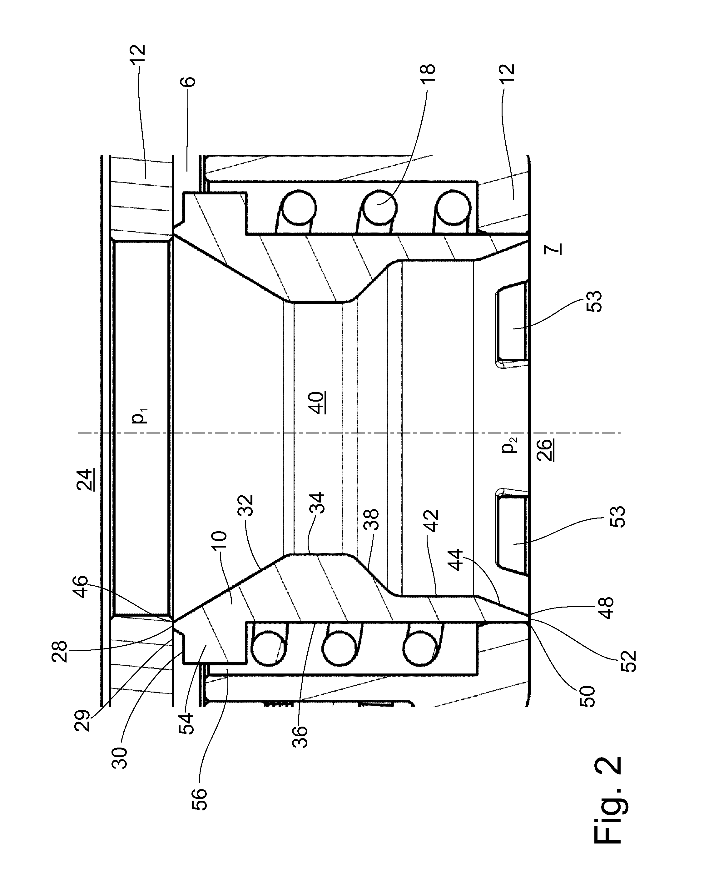
[0044]FIG. 2 shows the valve slide 10 in more detail. The v...


PUM


Abstract

Valve for a vibration damper having a valve housing and a valve slide movable in the valve housing to at least partially close at least one flow path of a fluid flowing through the valve. The valve has an input side and an output side. Pressure impingement surfaces of the valve slide are substantially equal for an opening pressure and for a closing pressure, and the valve slide has a restriction through which a pressure difference between opening pressure and closing pressure can be generated.

Description

CROSS REFERENCE TO RELATED APPLICATIONS[0001]This is a U.S. national stage of application No. PCT / EP2014 / 067792, filed on Aug. 21, 2014. Priority is claimed on German Application No. DE102013219443.9 filed Sep. 26, 2013, the content of which is incorporated here by reference.BACKGROUND OF THE INVENTION[0002]1. Field of the Invention[0003]The invention is directed to a valve for a vibration damper comprising a valve housing and a valve slide movable in the valve housing for at least partially closing at least one flow path of a fluid flowing through the valve, this valve having an input side and an output side.[0004]2. Description of the Prior Art[0005]It is known to use valves in vibration dampers. In two-tube vibration dampers, there is usually a base valve at the bottom of the working cylinder. Further, the piston can have a piston valve. In this case, the valves are compression valves.[0006]It is further known to provide two-tube dampers with an adjustable damping force so that a...

Claims


Application Information

Patent Timeline
IPC IPC(8): F16F9/34F16F9/19F16F9/512B60G13/08
CPCF16F9/34B60G13/08F16F9/19F16F2236/04B60G2202/24B60G2206/41F16F2238/04F16F9/5126
Inventor FORSTER, ANDREAS
Owner ZF FRIEDRICHSHAFEN AG
Why Eureka
Try Eureka