
Electronic Timepiece and Method for Controlling Display Operation of Electronic Timepiece

a technology of electronic timepiece and display operation, which is applied in the field of electronic timepiece and the control of display operation of electronic timepiece, can solve the problems of incorrect information reception, user undeadly unable to check the corrected time during the period, and mislead the user into believing the correct display tim

Active Publication Date: 2016-07-28
SEIKO EPSON CORP
View PDF3 Cites 1 Cited by
  • Summary
  • Abstract
  • Description
  • Claims
  • Application Information

AI Technical Summary

Benefits of technology

This solution enables users to quickly check corrected time without waiting for leap second information, informs them of impending leap second reception, and ensures accurate time display even with unsuccessful leap second information reception, reducing user confusion and improving reception rates.

Problems solved by technology

A long period therefore elapses from the initiation of the time correction process to corrected time display operation, which means that a user undesirably cannot check corrected time during the period.
However, displaying a result of unsuccessful leap second information reception as a reception result may mislead the user into believing that correct displayed time resulting from the successful time information reception is incorrect.
As a result, no displayed reception result representing unsuccessful reception will mislead the user into believing that the correct displayed time is incorrect.

Method used


Image

  • Electronic Timepiece and Method for Controlling Display Operation of Electronic Timepiece
  • Electronic Timepiece and Method for Controlling Display Operation of Electronic Timepiece
  • Electronic Timepiece and Method for Controlling Display Operation of Electronic Timepiece

Examples


first embodiment

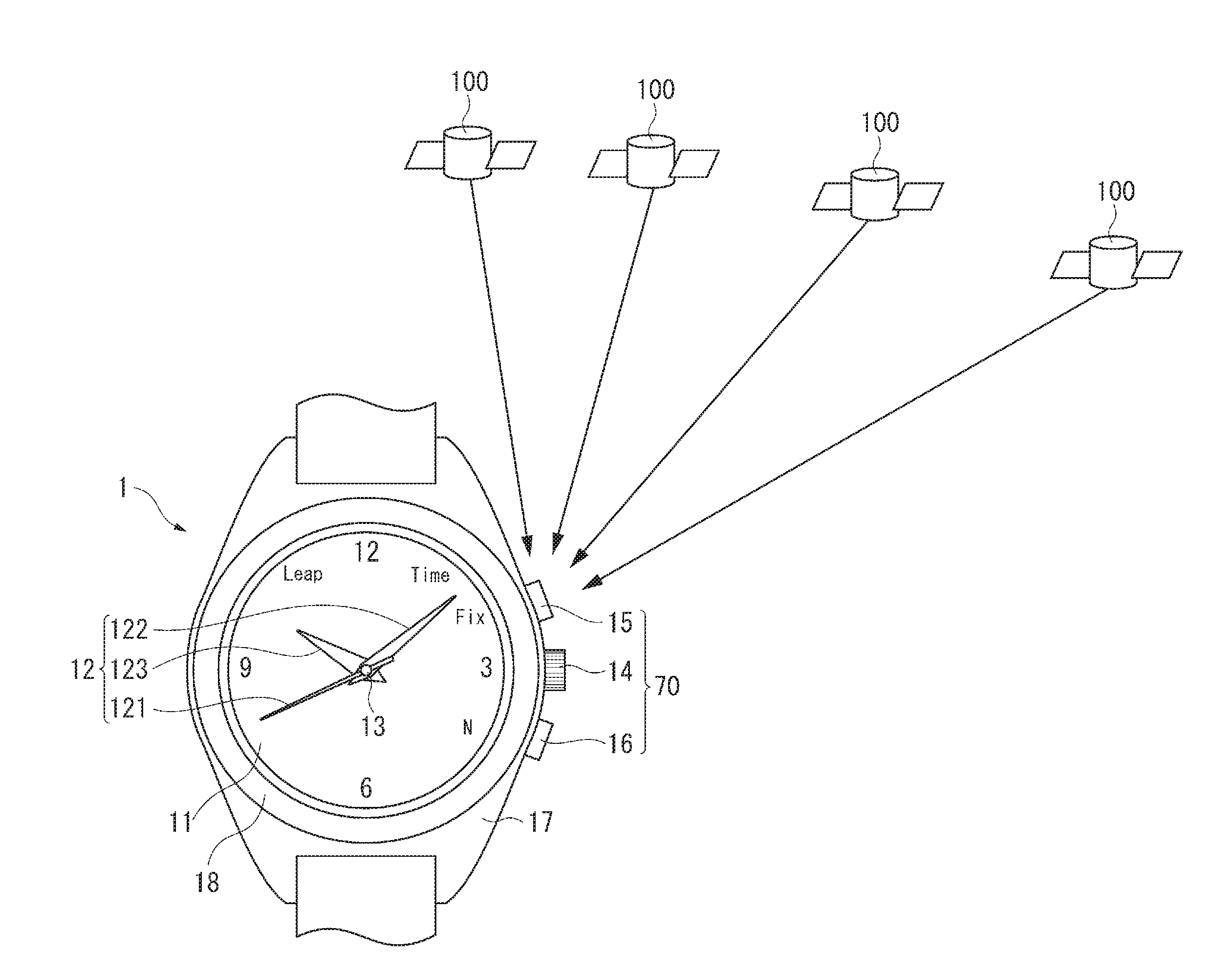
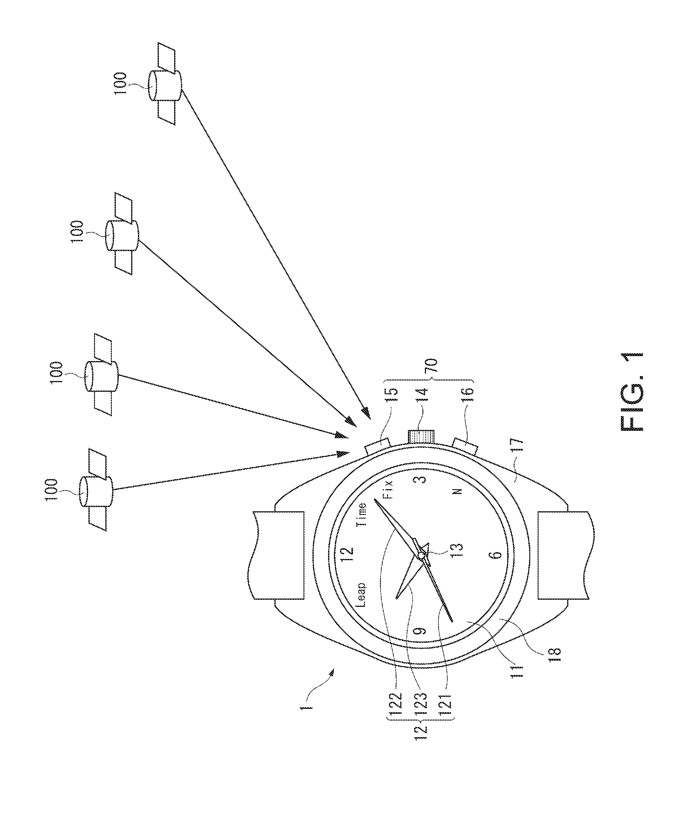
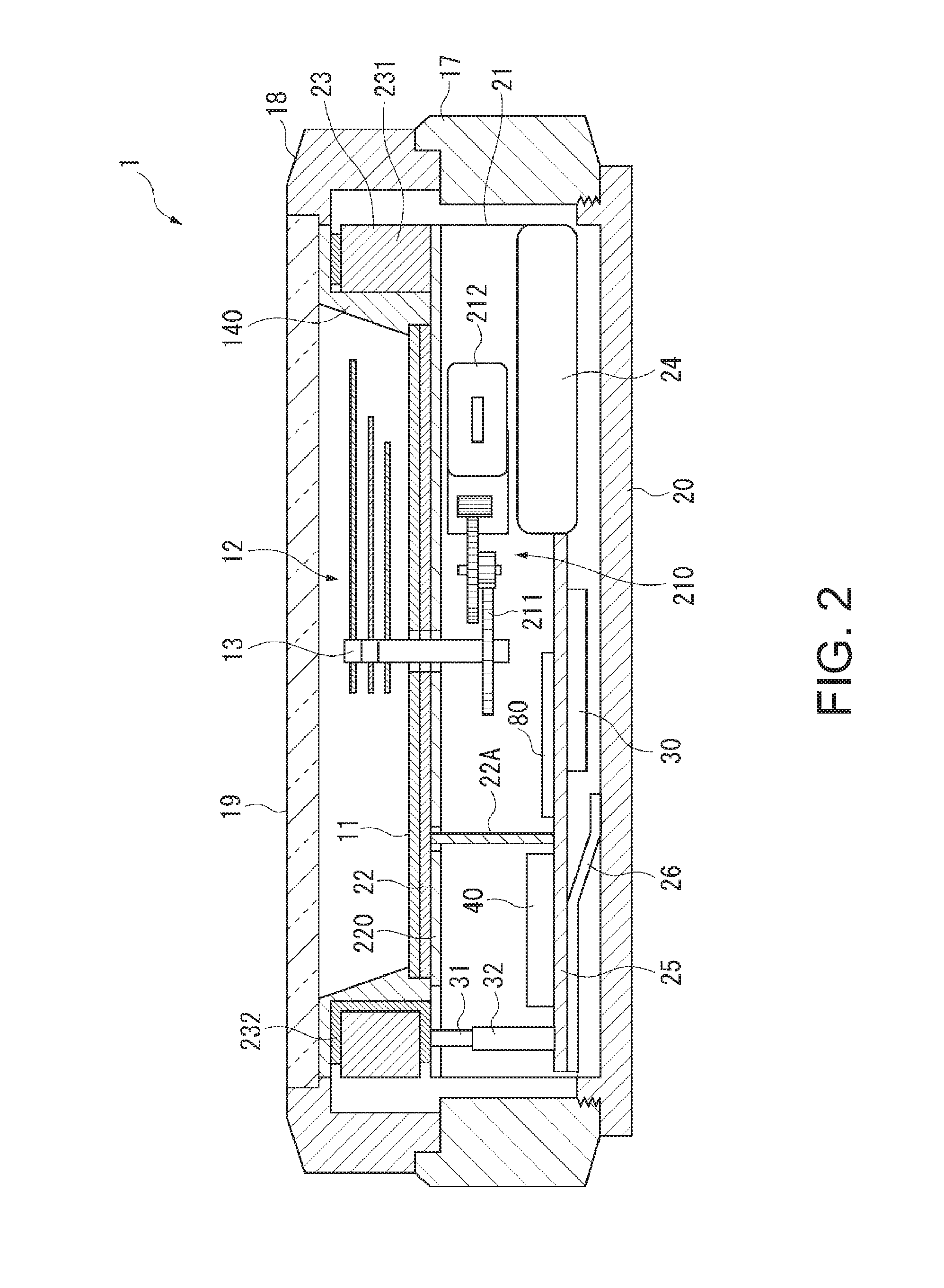
[0044]FIG. 1 is a front view of an electronic timepiece 1 according to a first embodiment of the invention, and FIG. 2 is a schematic cross-sectional view of the electronic timepiece 1.

[0045]A plurality of GPS satellites 100 go along a predetermined orbit around the earth up in the sky, and the electronic timepiece 1 receives a satellite signal from at least one of the GPS satellites 100 to acquire time information and receives satellite signals from at least three of the GPS satellites 100 to calculate positional information, as shown in FIG. 1. Each of the GPS satellites 100 is an example of a positional information satellite, and there are a plurality of GPS satellites around the earth up in the sky. At present, approximately 30 GPS satellites 100 go around the earth.

Electronic Timepiece

[0046]The electronic timepiece 1 is a wristwatch worn around a user' wrist, includes a dial 11 and indication hands 12, and clocks time and displays the clocked time.

[0047]A large part of the dial...

second embodiment

[0170]A second embodiment of the invention will next be described with reference to the drawings.

[0171]The second embodiment differs from the first embodiment in that in the reception process in the timing mode, the display control section 480 causes the display device 90 to display a result of time information reception. The second embodiment is the same as the first embodiment in terms of the other configurations.

[0172]FIGS. 10 and 11 are flowcharts showing the reception process in the timing mode of the electronic timepiece in the second embodiment.

[0173]The control device 40 carries out processes in SB11 to SB26, as shown in FIGS. 10 and 11. The processes in SB11 to SB24 are the same as the processes in SA11 to SA24 in the first embodiment and will not therefore be described.

[0174]In the first embodiment, when the timing section 410 fails to receive time information (No in SA13), the reception process is terminated.

[0175]In contrast, in the second embodiment, when the timing sec...


PUM


Abstract

An electronic timepiece includes a display section, a display control section, a reception section, a clock section, a timing section, a leap second acquisition section, a time correction section that corrects internal time information by using time information acquired by the timing section, and a leap second correction section that corrects the internal time information by using leap second information acquired by the leap second acquisition section. Ina case where the operation of the timing section is followed by the operation of the leap second acquisition section, the time correction section corrects the internal time information by using the time information acquired by the timing section, and the display control section causes the display section to display, before the leap second acquisition section acquires the leap second information, time based on the internal time information corrected by the time correction section.

Description

CROSS-REFERENCE TO RELATED APPLICATIONS[0001]This application is a continuation of, and claims priority under 35 U.S.C. §120 on, U.S. application no. 14 / 476,119, filed Sep. 3, 2014, which claims priority under 35 U.S.C. §119 on Japanese application no. 2013-187151, filed Sep. 10, 2013. Each such related application is incorporated by reference herein in its entirety.BACKGROUND[0002]1. Technical Field[0003]The present invention relates to an electronic timepiece that receives a satellite signal transmitted from a positional information satellite and corrects displayed time based on the signal and relates also to a method for controlling display operation of the electronic timepiece.[0004]2. Related Art[0005]To receive a satellite signal transmitted from a GPS (global positioning system) satellite and perform time correction based on the signal, it is necessary to acquire leap second information and reflect it in the time correction (see JP-A-2012-150061, for example).[0006]The electr...

Claims


Application Information

Patent Timeline
Patent Type & Authority Applications(United States)
IPC IPC(8): G04R20/04G04G19/00G04B19/04
CPCG04R20/04G04G19/00G04B19/04G04R20/06
Inventor AKIYAMA, TOSHIKAZU
Owner SEIKO EPSON CORP
Learn More