Portable charging station and method for charging portable electronic devices

a technology of electronic devices and portable charging stations, which is applied in the direction of electric vehicles, electric power, transportation and packaging, etc., can solve the problems of increasing the size of the power storage device, e.g., the battery, and the energy consumption of the sam

Inactive Publication Date: 2016-07-28
MACWILLIAMS GRAHAM T
View PDF8 Cites 3 Cited by
  • Summary
  • Abstract
  • Description
  • Claims
  • Application Information

AI Technical Summary

Benefits of technology

[0008]The present invention is directed to an apparatus and a method for charging a portable electrical device that features a switching system to selectively place an electrical storage subsystem in electrical communication with a source of light and a photovoltaic transducer. In one embodiment, the source of light is configured to direct optical energy upon a mounting surface and the photovoltaic transducer include optical sensors disposed on a sensing surface of the apparatus located opposite to the mounting surface. In another embodiment the optical sensor...

Problems solved by technology

However, with the increased computational power of the mobile electrical devices the energy usage of the same also increases.
This provides the deleterious effect of necessitating an increase in the size of the power storage device, e.g., battery.
This reduces one or more of the attractive features of these devices, ease of transport.
As th...

Method used


Image

  • Portable charging station and method for charging portable electronic devices
  • Portable charging station and method for charging portable electronic devices
  • Portable charging station and method for charging portable electronic devices

Examples


Embodiment Construction

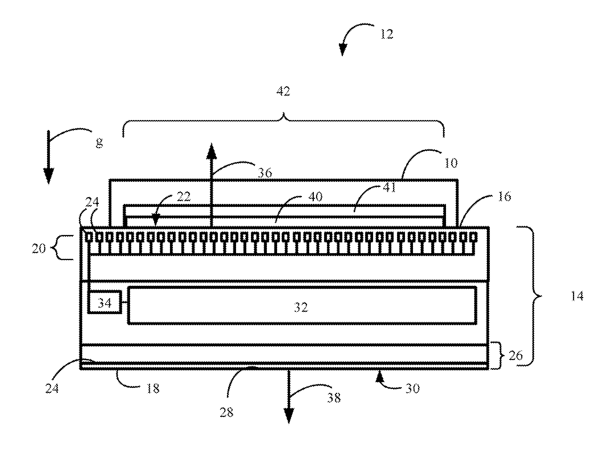
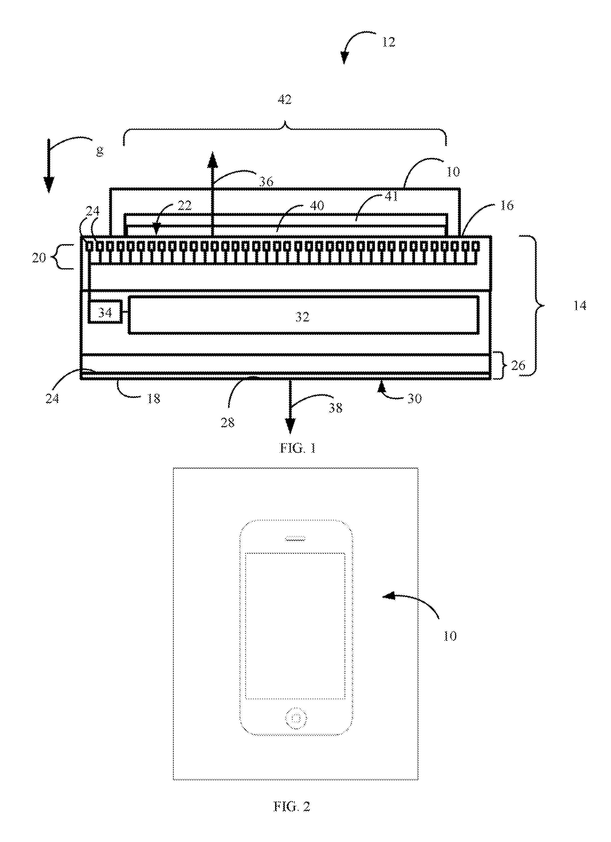
[0017]Referring to FIG. 1 one example of the present invention for use in charging an electrical device 10 includes a charging station 12. Charging station 12 includes a body 14 having opposed sides 16 and 18. A source of light 20 is included within body 14 to impinge optical energy upon side 16. In this manner, optical energy produced by source 20 travels toward a mounting surface 22 and impinges upon objects resting on mounting surface 22, such as electrical device 10. Thus, side 16 of body 14 is fabricated from a material that allows optical energy from source 20 to propagate therethrough. Although any type of light source may be employed, such as a single incandescent light (not shown) or fluorescent light (not shown). In the present example, however, source 20 consists of a plurality of point light sources 24. Any type of point light sources may be employed, such as light emitting diodes, laser diodes and the like.

[0018]Disposed proximate to side 18 is a photovoltaic transducer...


PUM


Abstract

The present invention is directed to an apparatus and a method for charging a portable electrical device that features a switching system to selectively place an electrical storage subsystem in electrical communication with a source of light and a photovoltaic transducer. In one embodiment, the source of light is configured to direct optical energy upon a mounting surface and the photovoltaic transducer include optical sensors disposed on a sensing surface of the apparatus disposed opposite to the mounting surface. In another embodiment the optical sensors are disposed in the mounting surface. An electrical storage subsystem is included in the apparatus that is selectively placed in electrical communication with one of the photovoltaic transducer and the source of light. The source of light may be a single source of light or a plurality of light emitters.

Description

[0001]The present invention relates to electricity production and more particularly to the charging of electronic devices not continuously coupled to an electrical grid.[0002]Historically, electricity is generated at a central location, commonly referred to as a power station, and transmitted over a network of transmission lines to substations located proximate to demand centers. This is referred to as an electrical grid. The substations typically step-down the voltage and transmit the stepped-down electricity to end users of the demand centers. With the advent of computing technology mobile devices using electricity have increased the demand for devices that use electricity and are not continuously coupled to the electrical grid. Examples of such devices include cameras, sensors, telephones, radios, tablet computers, wearable electronic devices, lighting systems, automobiles and drones just to name a few.[0003]Mobile electrical devices, such as cellular telephones, computing tablet...

Claims


Application Information

Patent Timeline
IPC IPC(8): H02J7/35
CPCH02J7/35Y02E10/56
Inventor MACWILLIAMS, GRAHAM T.
Owner MACWILLIAMS GRAHAM T
Why Eureka
Try Eureka