System for maintaining a pollutant controlled workspace

Active Publication Date: 2016-08-04
CARPE DIEM TECH
View PDF17 Cites 5 Cited by
  • Summary
  • Abstract
  • Description
  • Claims
  • Application Information

AI Technical Summary

Benefits of technology

The present invention is a system designed to control pollutants in a workspace. The system is effective in reducing the number of particles in the air, and can handle horizontal elements within the workspace. It is small in size, inexpensive to manufacture and operate, and allows for access to the workspace without compromising the quality of air retained therein.

Problems solved by technology

For instance, in the fabrication of certain semiconductor devices, optical components and pharmaceutical products, the presence of particulates as small as one micron can cause considerable defects, since the size of the product that is being produced may be comparable, or even significantly smaller, in size.
As a first shortcoming, pollutant controlled systems that rely upon a downward, laminar flow have been found to be ineffective when the workspace is populated with one or more horizontally disposed elements (e.g. tables, shelves or sections of a continuous flexible substrate, or web, driven horizontally by rollers through different treatment stations).
Specifically, downward displacement of debris across horizontal elements creates circulation issues within the workspace.
Additionally, the presence of horizontal elements causes turbulence in the clean air flow, resulting in the pressurization and swirling of particles throughout the workspace.
Accordingly, particulates present throughout the workspace can eventually fall by gravity or be attracted electrostatically onto potentially sensitive surfaces, resulting in less than optimal production levels.
As a second shortcoming, pollutant controlled systems that rely upon a downward, laminar flow have been found to be ineffective when the enclosure is opened (e.g. through a door or window) in order to access the pollutant controlled workspace.
Most notably, opening the enclosure not only causes clean air to prematurely escape from the workspace but also contaminated air to enter into the workspace, thereby creating inefficiencies.

Method used


Image

  • System for maintaining a pollutant controlled workspace
  • System for maintaining a pollutant controlled workspace
  • System for maintaining a pollutant controlled workspace

Examples


example 1

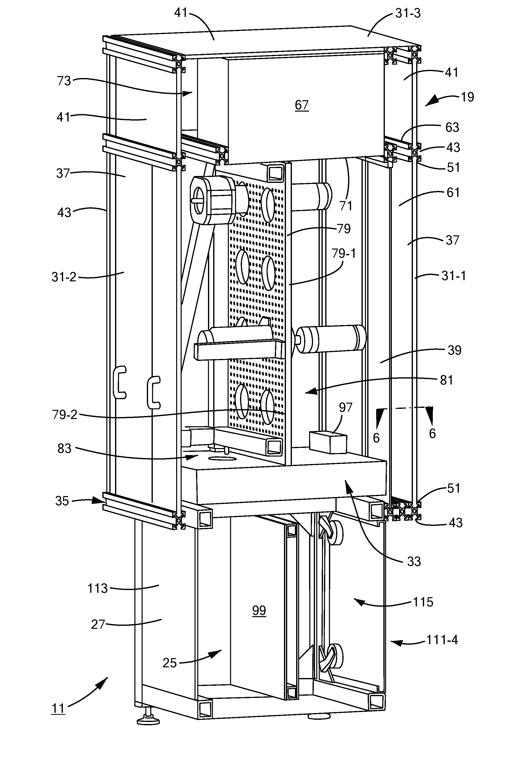
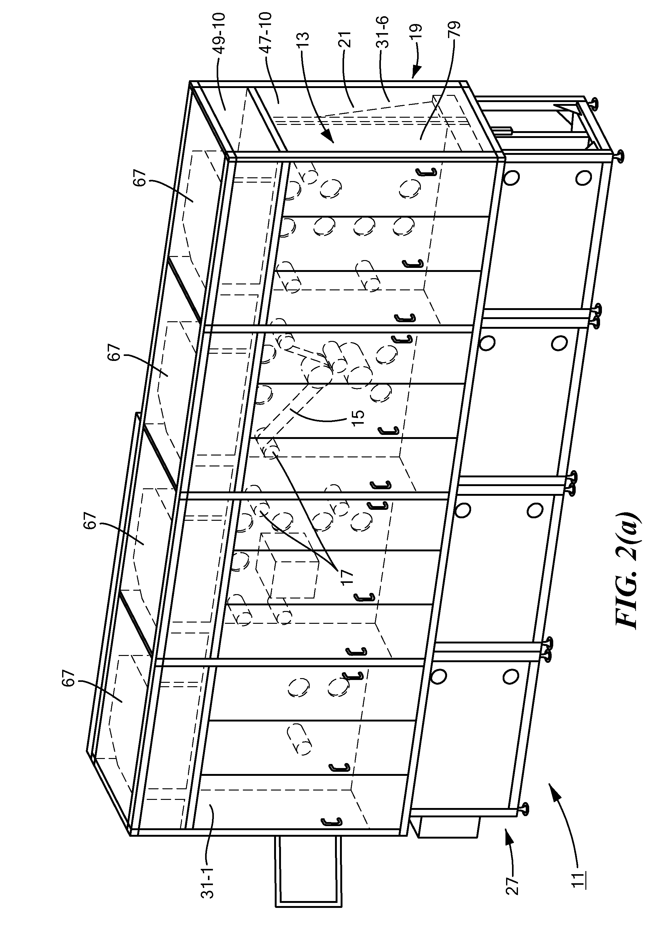
[0129]With fans 65, 69 and 77 operating, exterior panels 37 closed, and interior panels 39 removed, the average particle count recorded within selected areas of each module 29 for particles at least 0.5 μm in size was 125.9375. Table 1 below represents the data collected under the aforementioned test conditions.

TABLE 1ModuleModuleModuleModuleModeConditionSize29-129-229-329-4MAll Doors Closed0.5μ1039762196No Screens Bottom0.7μ30342756LeftMAll Doors Closed0.5μ6416313134No Screens Bottom0.7μ22311535RightMAll Doors Closed0.5μ10711057331No Screens Upper0.7μ503117102LeftMAll Doors Closed0.5μ7621148180No Screens Upper0.7μ2884045Right

example 2

[0130]With fans 65, 69 and 77 continuing to operate, exterior panels 37 opened, and interior panels 39 removed, the average particle count recorded within each module 29 for particles at least 0.5 μm in size increased to 978.3125. Table 2 below represents the data collected under the aforementioned test conditions.

TABLE 2ModuleModuleModuleModuleModeConditionSize29-129-229-329-4MAll Doors Closed0.5μ1039762196No Screens Bottom0.7μ30342756LeftMAll Doors Closed0.5μ6416313134No Screens Bottom0.7μ22311535RightMAll Doors Closed0.5μ10711057331No Screens Upper0.7μ503117102LeftMAll Doors Closed0.5μ7621148180No Screens Upper0.7μ2884045Right

[0131]As can be seen, the average particle count from example 1 to example 2 increased by a factor of 7.7, which is indicative of the effectiveness of airtight enclosure 19 in preventing outside contaminants from entering into workspace 81.

example 3

[0132]With both exterior and interior panels 37 and 39 installed and positioned closed, all fans 65, 69, and 77 were set to operate at 50% of their maximum speed. After waiting a suitable time period for clean air to circulate through workspace 81, the average particle count recorded within each module 29 for particles at least 0.5 μm in size was 79.5625. Table 3 below represents the data collected under the aforementioned test conditions.

TABLE 3ModuleModuleModuleModuleModeConditionSize29-129-229-329-4MAll Doors Closed0.5μ12778922All Screens Bottom0.7μ6441411LeftMAll Doors Closed0.5μ100697795All Screens Bottom0.7μ42274055RightMAll Doors Closed0.5μ103806546All Screens Upper0.7μ49353821LeftMAll Doors Closed0.5μ10584110103All Screens Upper0.7μ52465955Right


PUM

PropertyMeasurementUnit
Pressureaaaaaaaaaa
Flow rateaaaaaaaaaa
Efficiencyaaaaaaaaaa

Abstract

A system for maintaining a pollutant controlled workspace includes an airtight enclosure with a front access window. A set of impermeable exterior panels and a set of permeable interior panels are slidably mounted within the access window in a spaced apart relationship. Regulated either through a manual control panel or programmable controller, a fan filter unit treats a supply of source air and delivers the filtered air down into a narrow vertical airflow channel located between the exterior and interior panels. Once a suitable amount of pressure accumulates, the treated air penetrates into the workspace as a horizontal laminar flow. Any particulates present in the workspace are drawn rearward by the laminar flow and are trapped behind a multi-apertured back board. The contaminant air is then drawn from a low pressure return located behind the back board and into the fan filter unit for recirculation within the enclosure.

Description

FIELD OF THE INVENTION[0001]The present invention relates generally to the fabrication of products that are highly sensitive to the presence of particulates and, more particularly, to enclosed systems that are designed to maintain a pollutant controlled, or clean, workspace suitable for the fabrication of such products.BACKGROUND OF THE INVENTION[0002]In the manufacture of extremely fine detailed structures, a workspace is typically required that has a low level of environmental pollutants, such as dust, microbes or chemical vapors. For instance, in the fabrication of certain semiconductor devices, optical components and pharmaceutical products, the presence of particulates as small as one micron can cause considerable defects, since the size of the product that is being produced may be comparable, or even significantly smaller, in size.[0003]To minimize the risk of particulate contamination, sensitive products are commonly manufactured within a pollutant controlled system. As defin...

Claims


Application Information

Patent Timeline
IPC IPC(8): F24F11/00B01D46/00B01D46/44F24F13/28F24F13/20
CPCF24F11/0079F24F13/28F24F13/20F24F2011/0023B01D46/0002F24F2011/0091B01D46/442F24F2110/64F24F3/163H01L21/67017H01L21/67173Y02B30/70B08B15/023Y02A50/20
Inventor BERG, JOHN S.BENCHEV, DIMITURBLACKBURN, NICOLE ELIZABETH
Owner CARPE DIEM TECH
Why Eureka
Try Eureka