Resonant power supply with self tuning

a self-tuning, power supply technology, applied in the direction of power conversion systems, power electronics conversion, electrical apparatus, etc., can solve the problems of difficult operation of the supply, complex controllers, and relatively difficult start-up of this form of inverter, and achieve the effect of large transient voltages

Active Publication Date: 2016-08-04
AUCKLAND UNISERVICES LTD
View PDF21 Cites 7 Cited by
  • Summary
  • Abstract
  • Description
  • Claims
  • Application Information

AI Technical Summary

Benefits of technology

[0027]Switching the control resistor into or out of the resonant circuit reduces or increases the resonant voltage to allow a controlled

Problems solved by technology

The start-up of this form of inverter is relatively difficult, requiring a complex controller.
When operating at high frequencies a conventional power supply (not shown) has problems since as the frequency gets higher it becomes increasingly difficult to operate the supply as the required dV/dt and dl/dt tr

Method used


Image

  • Resonant power supply with self tuning
  • Resonant power supply with self tuning
  • Resonant power supply with self tuning

Examples


Embodiment Construction

[0064]Inverters are basic building blocks for many modern power inverters. The new inverters described in this document can be used in various applications where high frequency voltage or current generation is required. These applications include but not limited to inductively coupled contactless power transfer, induction heating, DC-DC converters, uninterruptible power supplies for example.

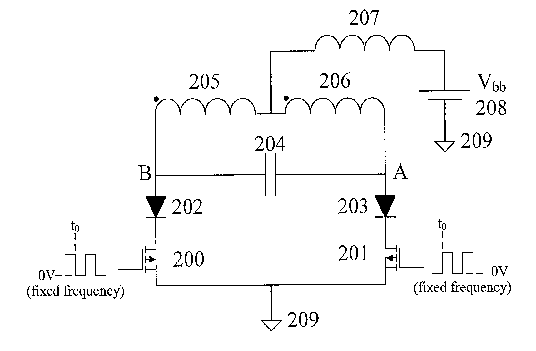
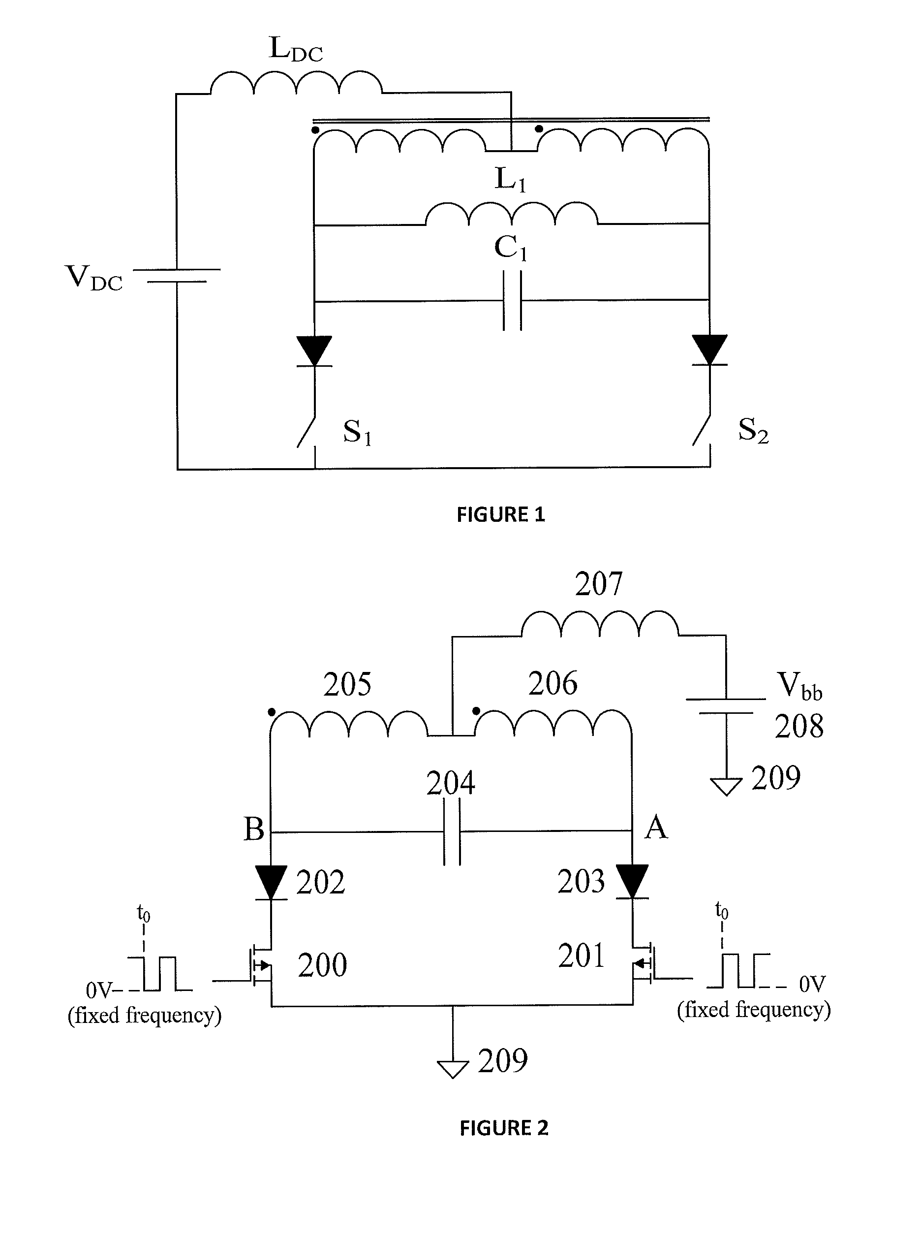
[0065]The invention will now be described, beginning with an explanation of a known inverter which is shown in FIG. 2. This circuit is essentially the same as that in FIG. 1 but now there is no phase splitting transformer and two coupled inductors 205 and 206 are used instead. There is also no independent resonant inductor—the same inductors 205 and 206 perform this task as well. In both these circuits FIG. 1 and FIG. 2 switching the transistors in response to the natural oscillations of the circuit can cause bi-furcation on critical loads and then the power available to the IPT system is greatly...


PUM


Abstract

This invention relates to current-fed resonant inverters for electrical power applications to change direct current (DC) into alternating current (AC). One application of the invention is to power supplies for inductive power transfer (IPT) systems. There is provided a resonant inverter including an input for supply of current from a DC power source, a resonant circuit including two coupled inductive elements and a tuning capacitance, the inductive elements being arranged to split current from the power source; a first switching means comprising two switching devices operable in substantially opposite phase to alternately switch current from the power source into the inductive elements; and a second switching means to selectively switch one or more control capacitances into or out of the resonant circuit dependent on a power factor of the resonant circuit.

Description

FIELD OF THE INVENTION[0001]This invention relates to current-fed resonant inverters for electrical power applications to change direct current (DC) into alternating current (AC). One application of the invention is with power supplies for inductive power transfer (IPT) systems.BACKGROUND[0002]Inverters have numerous applications in electrical power supplies including the production of alternating current power supplies, for example, when used as an inverter to convert a DC voltage into an AC voltage supply (e.g. an uninterruptible power supply). They may also be used in internal stages of DC to DC converters, induction heating, microwave generation, surface detection, medical experimentation, high frequency radio systems, IPT systems, etc.[0003]A circuit schematic for a known push-pull current fed resonant inverter is shown in FIG. 1. The operation of such inverters is discussed in U.S. Pat. No. 5,450,305 the contents which are incorporated herein by reference. These resonant inver...

Claims


Application Information

Patent Timeline
IPC IPC(8): H02M7/537H02M1/42H02M1/44H02M1/36
CPCH02M1/34H02M1/36H02M2007/4815H02M1/44H02M7/537H02M1/42Y02B70/10H02M7/48H02M7/4815
Inventor BOYS, JOHN TALBOTCOVIC, GRANT ANTHONY
Owner AUCKLAND UNISERVICES LTD
Why Eureka
Try Eureka