Resonant power supply with self tuning

a self-tuning, power supply technology, applied in the direction of power conversion systems, power electronics conversion, electrical apparatus, etc., can solve the problems of difficult operation of the supply, complex controllers, and relatively difficult start-up of this form of inverter, and achieve the effect of large transient voltages

Active Publication Date: 2019-05-28
AUCKLAND UNISERVICES LTD
View PDF26 Cites 0 Cited by
  • Summary
  • Abstract
  • Description
  • Claims
  • Application Information

AI Technical Summary

Benefits of technology

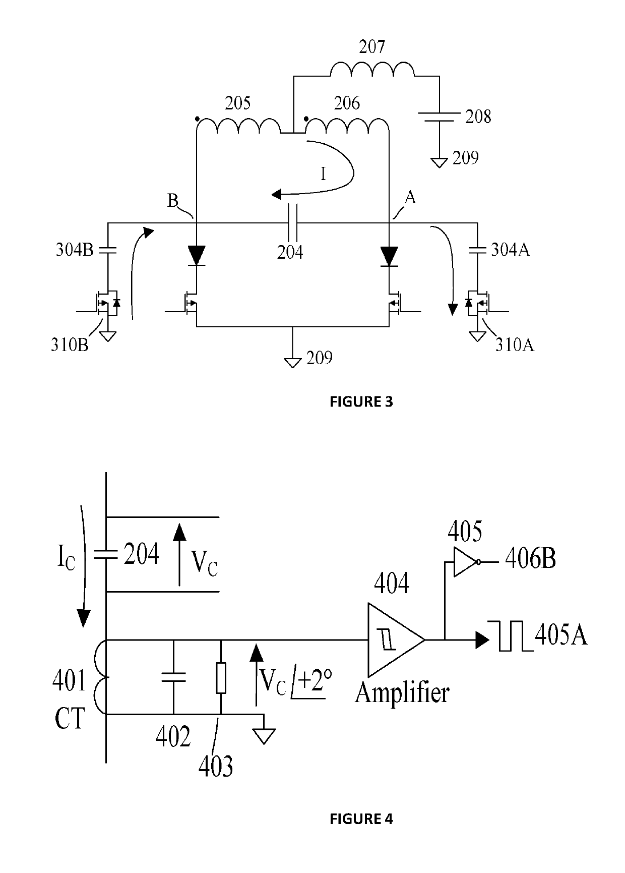
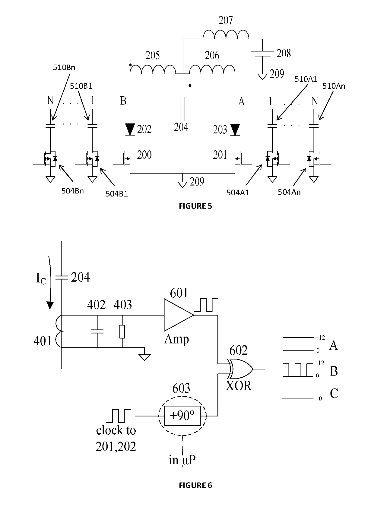
[0012]Such an arrangement may be used to reduce high peak voltages in the resonant circuit that may otherwise occur due to lack of tuning or low power factor. The presence of such high peak voltages, especially at high frequency where the rate of change in voltage would then be very high, can damage the switching devices. Tuning the inverter also optimises the power transferred for example in an IPT (inductive power transfer) secondary such as an electric vehicle. Selective switching of the control capacitors enables dynamic correction of the power factor which may vary due to external factors such as secondary load changes and / or coupling changes, for example due to a changing distance between the inductive elements and a secondary coil on an electric car.
[0018]In an embodiment, the resonant inverter may comprise a buck control circuit coupled between an input current source and the inductive elements, the buck control circuit having a diode and buck control switch having a duty cycle which is controlled in order to adjust the voltage across the tuning capacitor. This arrangement may be used to start and stop the resonant current, and may also be used to reduce the peak voltage when the resonant circuit is not tuned. This development offers better control options and additionally can be implemented with only three switches making this a cheap option.
[0020]The embodiments can provide a fixed frequency sinusoidal resonant inverter comprising using a digitally switchable power capacitor whereby the tuning frequency can be closely controlled to be near to the operating frequency at all times and the circuit operates at high efficiency with low distortion waveforms such that the switching voltage and the output current have a high power factor under steady state and dynamic conditions.
[0023]This arrangement can also be used to reduce high peak voltages in the resonant circuit due to lack of tuning or low power factor. It can be implemented simply with a total of three switching devices comprising the first switching means of two transistors and the Buck switching means comprising one transistor, and is very low cost. Thus the duty cycle of the Buck switching means is controlled in order to reduce the DC supply voltage to the inverter in response to the switching of the first switching devices being out of phase with the resonant circuit resonating current. Alternatively or additionally, the duty cycle may be controlled in order to stop or start the resonant circuit.
[0026]The embodiments can provide a fixed frequency resonant inverter that operates at high efficiency with constant frequency but without tuning and errors are accommodated within the circuit but without high distortion or significant losses and the circuit can be shut down when required without damage.
[0028]Switching the control resistor into or out of the resonant circuit reduces or increases the resonant voltage to allow a controlled change between normal resonant operation and OFF, without large transient voltages being incurred that could damage the switching devices.

Problems solved by technology

The start-up of this form of inverter is relatively difficult, requiring a complex controller.
When operating at high frequencies a conventional power supply (not shown) has problems since as the frequency gets higher it becomes increasingly difficult to operate the supply as the required dV / dt and dl / dt transients are so high that operating the power supply is problematic.
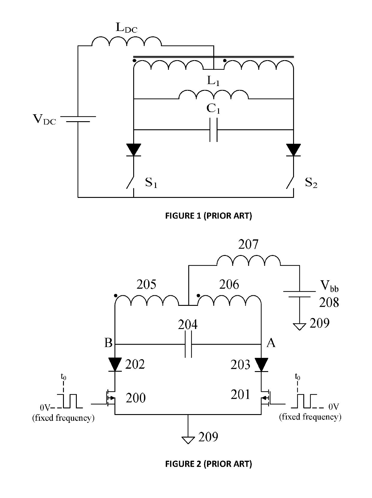
However a difficulty with this circuit (FIG. 1) is maintaining an operating frequency in response to changes in the reactive load on the inverter and in particular maintaining a required power factor since the circuit can easily bifurcate.

Method used


Image

  • Resonant power supply with self tuning
  • Resonant power supply with self tuning
  • Resonant power supply with self tuning

Examples


Embodiment Construction

[0065]Inverters are basic building blocks for many modern power inverters. The new inverters described in this document can be used in various applications where high frequency voltage or current generation is required. These applications include but not limited to inductively coupled contactless power transfer, induction heating, DC-DC converters, uninterruptible power supplies for example.

[0066]The invention will now be described, beginning with an explanation of a known inverter which is shown in FIG. 2. This circuit is essentially the same as that in FIG. 1 but now there is no phase splitting transformer and two coupled inductors 205 and 206 are used instead. There is also no independent resonant inductor—the same inductors 205 and 206 perform this task as well. In both these circuits FIG. 1 and FIG. 2 switching the transistors in response to the natural oscillations of the circuit can cause bi-furcation on critical loads and then the power available to the IPT system is greatly...


PUM


Abstract

This invention relates to current-fed resonant inverters for electrical power applications to change direct current (DC) into alternating current (AC). One application of the invention is to power supplies for inductive power transfer (IPT) systems. There is provided a resonant inverter including an input for supply of current from a DC power source, a resonant circuit including two coupled inductive elements and a tuning capacitance, the inductive elements being arranged to split current from the power source; a first switching means comprising two switching devices operable in substantially opposite phase to alternately switch current from the power source into the inductive elements; and a second switching means to selectively switch one or more control capacitances into or out of the resonant circuit dependent on a power factor of the resonant circuit.

Description

PRIORITY CLAIM TO RELATED APPLICATIONS[0001]This application is a U.S. national stage application filed under 35 U.S.C. § 371 from International Application Serial No. PCT / NZ2014 / 000196, which was filed 10 Sep. 2014, and published as WO2015 / 038010 on 19 Mar. 2015, and which claims priority to New Zealand Application No. 615464, filed 12 Sep. 2013, which applications and publication are incorporated by reference as if reproduced herein and made a part hereof in their entirety, and the benefit of priority of each of which is claimed herein.FIELD OF THE INVENTION[0002]This invention relates to current-fed resonant inverters for electrical power applications to change direct current (DC) into alternating current (AC). One application of the invention is with power supplies for inductive power transfer (IPT) systems.BACKGROUND[0003]Inverters have numerous applications in electrical power supplies including the production of alternating current power supplies, for example, when used as an...

Claims


Application Information

Patent Timeline
Patent Type & Authority Patents(United States)
IPC IPC(8): H02M7/537H02M1/34H02M1/36H02M1/42H02M1/44H02M7/48
CPCH02M7/537H02M1/34H02M1/42H02M1/44H02M1/36H02M2007/4815Y02B70/10H02M7/48H02M7/4815
Inventor BOYS, JOHN TALBOTCOVIC, GRANT ANTHONY
Owner AUCKLAND UNISERVICES LTD
Why Eureka
Try Eureka