Gas sensor control device
a control device and sensor technology, applied in the direction of electric control, instruments, machines/engines, etc., can solve the problems of excessive voltage applied to the sensor element, and possible bad influence on etc., to suppress the deterioration of the solid electrolyte body
- Summary
- Abstract
- Description
- Claims
- Application Information
AI Technical Summary
Benefits of technology
Problems solved by technology
Method used
Image
Examples
first embodiment
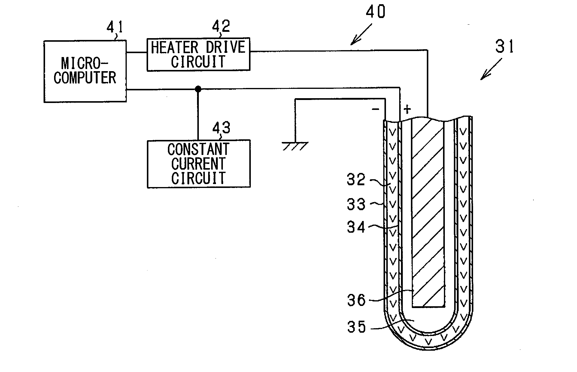
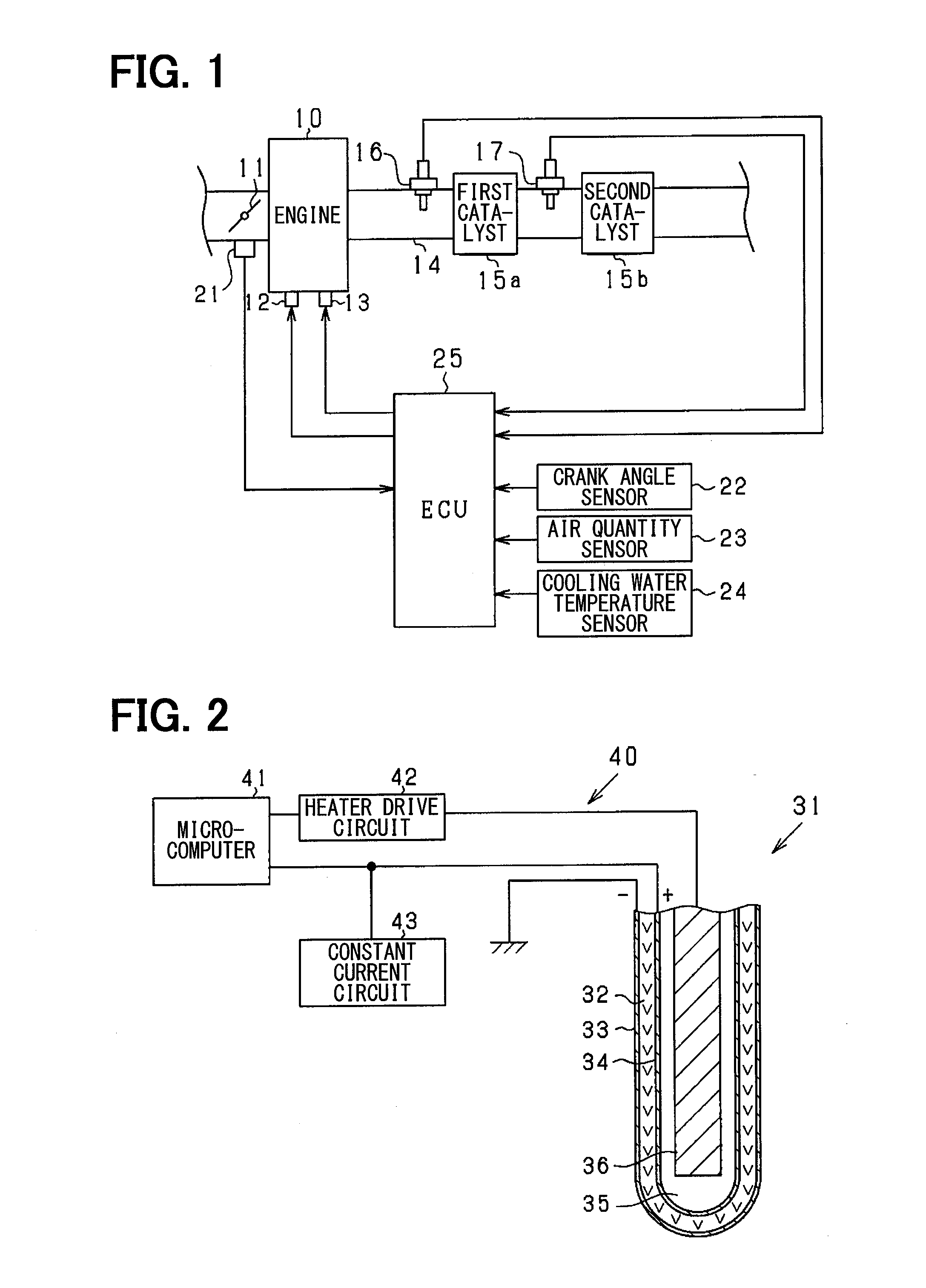
[0034]Next, an embodiment of a gas sensor control device according to the present disclosure will be described referring to drawings. This embodiment concerns an engine control system which uses a gas sensor located on the exhaust pipe of an on-vehicle engine (internal combustion engine) to perform various controls, etc. of the engine according to output of the gas sensor. The control system, centered on an electronic control unit (ECU), performs control of the amount of fuel injection, control of ignition timing and so on. FIG. 1 is a block diagram which shows the general configuration of the system.
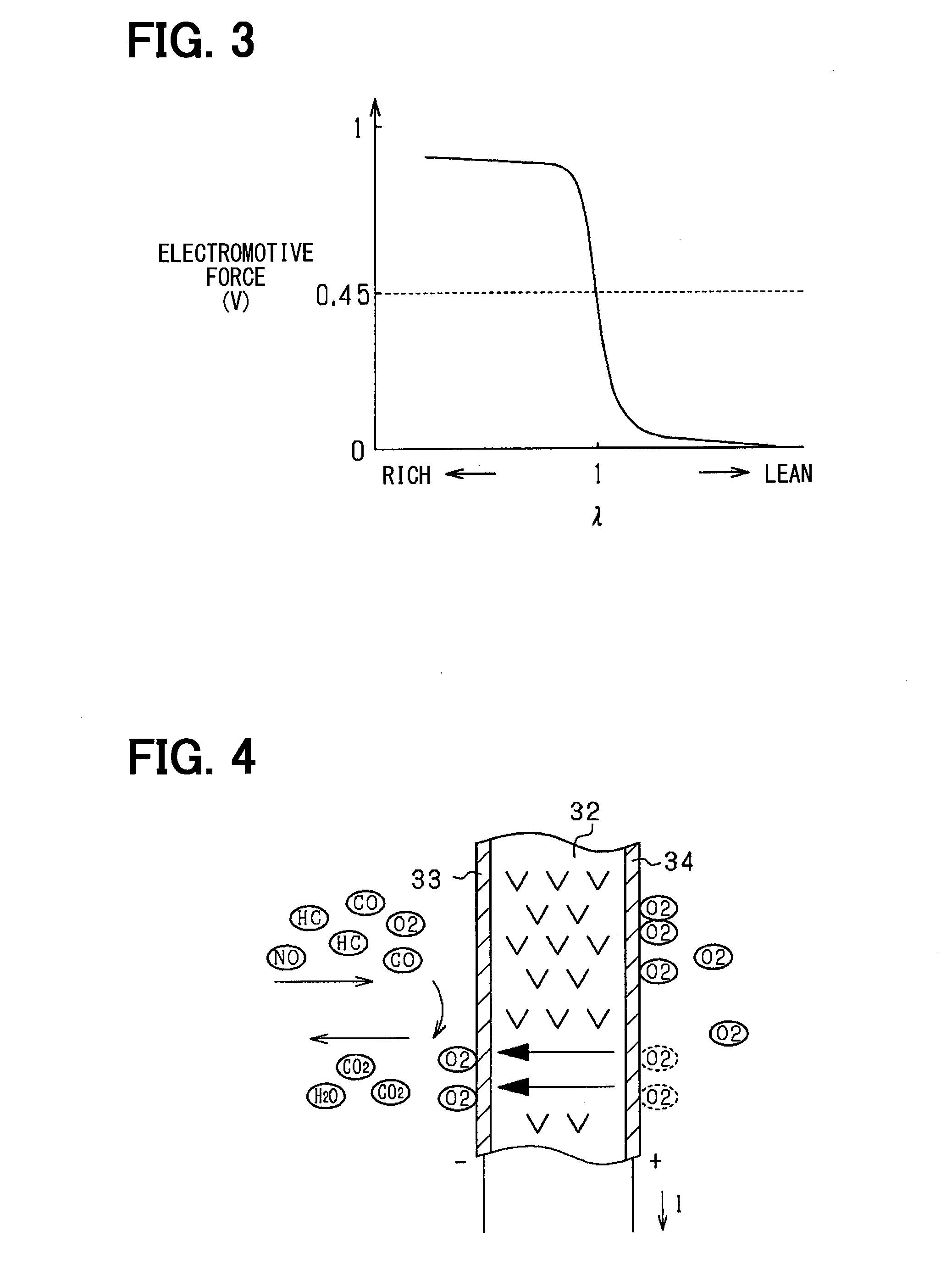
[0035]In FIG. 1, an engine 10 is, for example, a gasoline engine which includes a throttle valve 11 that is electronically controlled, a fuel injection valve 12, and an ignition device 13. An exhaust pipe 14 of the engine 10 is provided with catalysts 15a and 15b as exhaust gas purifying devices. The exhaust pipe 14 corresponds to an exhaust section. The catalysts 15a and 15b are, for e...
second embodiment
[0085]In the second embodiment, for the supply of constant current by the constant current circuit 43, an allowable resistance range for the element resistance in which the supply of constant current is allowed is set. When the element resistance Ra is determined to be larger than an allowable range, the constant current supplied by the constant current circuit 43 is restricted for the reason that a bad influence on the solid electrolyte layer 32 may occur. The concrete arrangement is described below. In this example, the constant current is set as a variable according to the engine operation condition, etc. FIG. 12 is a flowchart which shows the constant current control process and this process is repeated by the microcomputer 41 in a given cycle.
[0086]In FIG. 12, at S31 the microcomputer 41 determines whether or not the constant current is being supplied by the constant current circuit 43. At S32, the microcomputer 41 determines whether or not cold start of the engine 10 or fuel c...
third embodiment
[0089]In the third embodiment, the gas sensor on the upstream of the first catalyst 15a in FIG. 1 is an O2 sensor 16A of the same electromotive force output type as the O2 sensor 17 on the downstream. The ECU 25 performs air-fuel ratio feedback control according to detection signals from the two O2 sensors 16A and 17A on the upstream and downstream with the first catalyst 15a between them. In this case, the ECU 25 performs main feedback control so that the front air-fuel ratio detected by the upstream O2 sensor 16A becomes a target air-fuel ratio (for example, theoretical air-fuel ratio), and also performs sub-feedback control to set the delay time from when the front air-fuel ratio becomes rich or lean until it is actually determined to be rich or lean, as a variable according to the rear air-fuel ratio detected by the downstream O2 sensor 17. Next, the main feedback control and sub-feedback control will be briefly explained.
[0090]At the time when the rich delay time has elapsed si...
PUM
| Property | Measurement | Unit |
|---|---|---|
| electromotive force | aaaaa | aaaaa |
| electromotive force | aaaaa | aaaaa |
| constant voltage | aaaaa | aaaaa |
Abstract
Description
Claims
Application Information
 - R&D
- Intellectual Property
- Life Sciences
- Materials
- Tech Scout
- Unparalleled Data Quality
- Higher Quality Content
- 60% Fewer Hallucinations
Browse by: Latest US Patents, China's latest patents, Technical Efficacy Thesaurus, Application Domain, Technology Topic, Popular Technical Reports.
© 2025 PatSnap. All rights reserved.Legal|Privacy policy|Modern Slavery Act Transparency Statement|Sitemap|About US| Contact US: help@patsnap.com


