Engine Starter Attachment for Battery Operated Drill/Driver Gun

Active Publication Date: 2016-08-11
K SQUARE MACHINE WORKS
View PDF11 Cites 7 Cited by
  • Summary
  • Abstract
  • Description
  • Claims
  • Application Information

AI Technical Summary

Benefits of technology

[0008]The present invention features a shaft attached to a cylinder which accepts a rubber or silicone insert that fits onto the nose cone of a model airplane or cone adapter of any small internal combustion engine. The shaft is attached to the cylinder by means of a one way clutch which allows the torque of the drill / driver gun to be applied to a gasoline powered engine including a model airplane engine while also allowing the engine to speed up faster than the drill / driver is spinning when the engine starts to run on its own.
[0009]A device used to adapt a commercially available battery powered drill / driver gun for use as a starter for internal combustion powered engines including model airplane engines. A shaft is attached to a cylinder into which a rubber or silicone adapter is inserted. The rubber or silicone adapter is fitted onto the nose cone of a model airplane or a cone adapter of any small internal combustion engine. The shaft and cylinder are attached by means of a one way clutch. The one way clutch allows the gear driven drill / driver gun to turn the cylinder with the necessary torque to crank the internal combustion engine while allowing the cylinder to be spin as fast as the engine when the engine starts to operate under its own power. This feature allows the device to turn the engine drive crankshaft with sufficient torque to start the engine while not prohibiting the engine from rotating faster than the cylinder attached to the drill / driver gun when the engine stats running.

Problems solved by technology

This gear drive provides the torque to turn an internal combustion engine crankshaft and piston; however, this same gear drive prohibits the engine from turning faster than the drill / driver gun at the moment the engine catches and starts to run on its own.

Method used


Image

  • Engine Starter Attachment for Battery Operated Drill/Driver Gun
  • Engine Starter Attachment for Battery Operated Drill/Driver Gun
  • Engine Starter Attachment for Battery Operated Drill/Driver Gun

Examples


Embodiment Construction

[0017]The present invention will now be described in terms of the presently preferred embodiment thereof as illustrated in the drawings. Those of ordinary skill in the art will recognize that many obvious modifications may be made thereto without departing from the spirit or scope of the present invention.

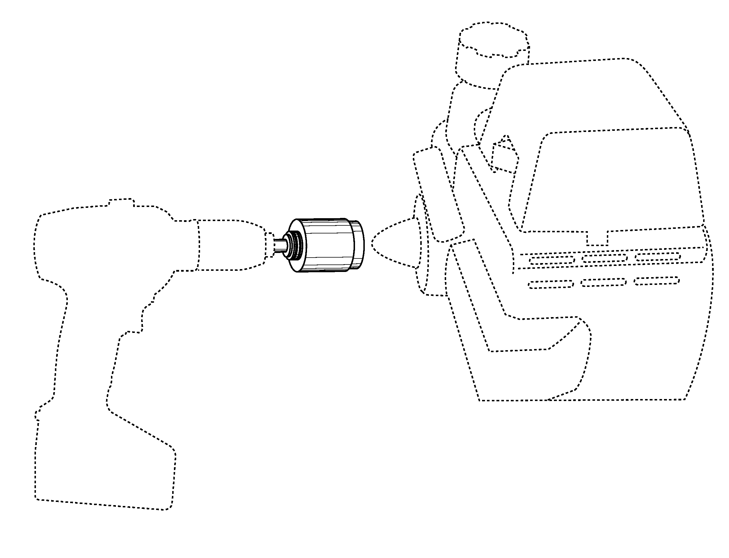
[0018]The present invention is directed to a device for a commercially available battery operated drill / driver gun. Specifically, the device is a tool designed to be set in the chuck of the drill driver / gun. FIG. 4. When affixed to the drill / driver gun, the device converts a standard battery operated drill / driver gun into a starter for an internal combustion engine including but not limited to a model airplane internal combustion engine. FIG. 5 and FIG. 6.

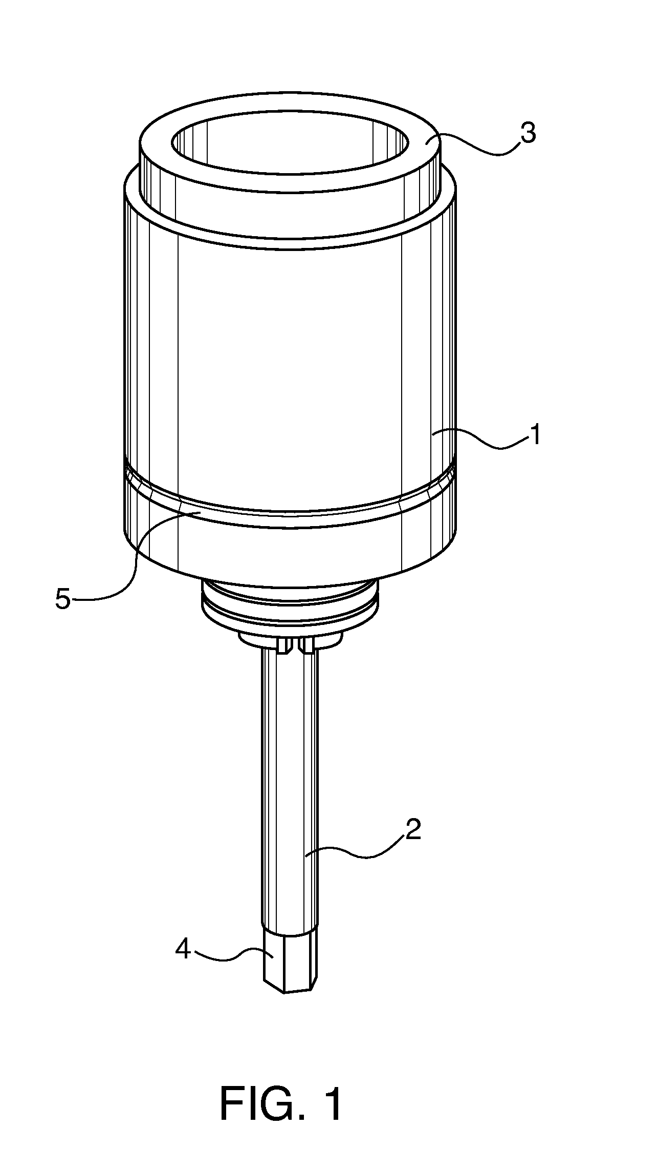
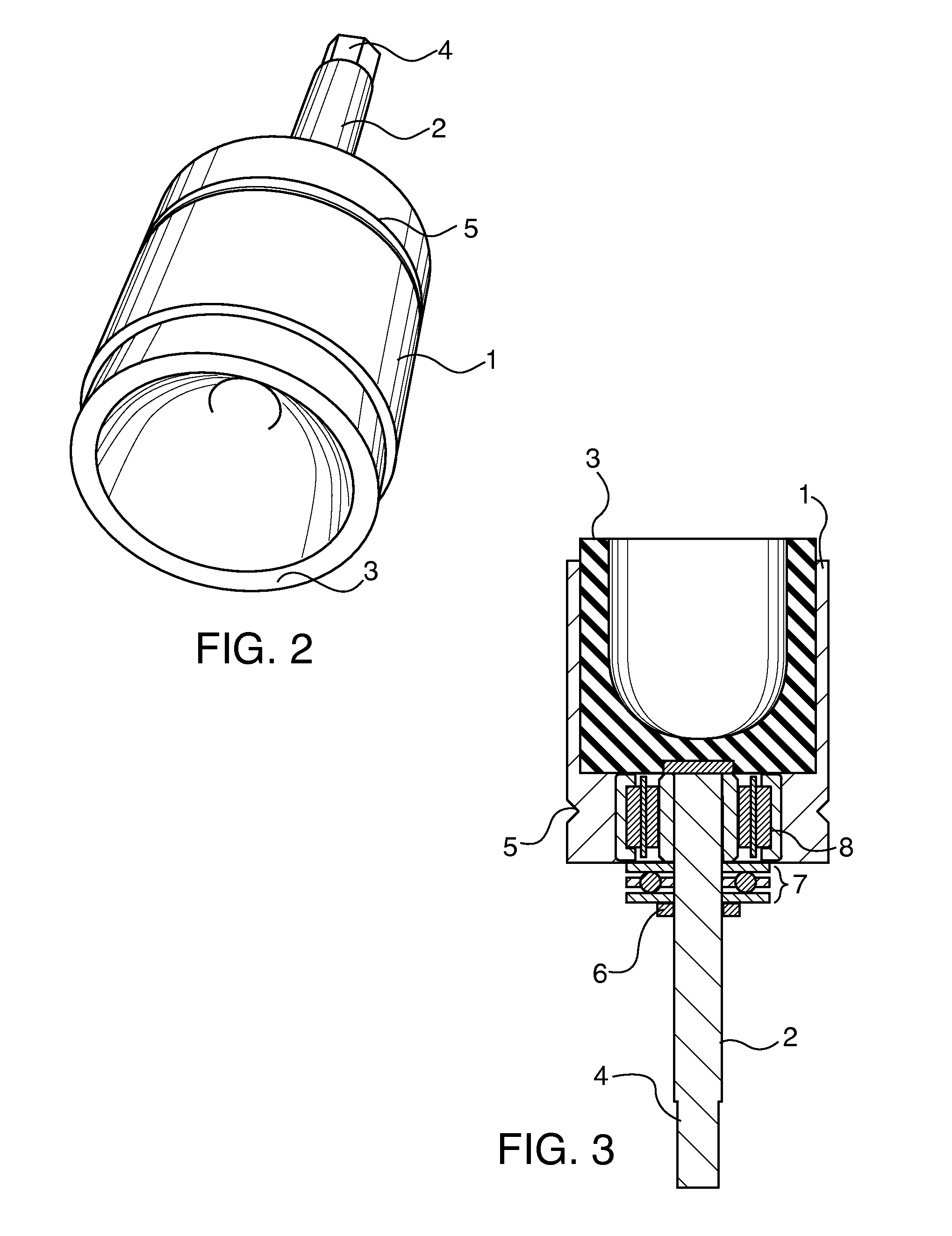
[0019]The device comprises a shaft (2) affixed to a cylinder (1). FIG. 1. The cylinder (1) is made of aluminum, plastic or other similar material which is machineable and light weight. A rubber or silicone insert (3) is pressed in...


PUM


Abstract

A device designed to be a fixture for a commercially available battery operated drill/driver gun used to start an internal combustion engine such as a model airplane engine by pressing the device onto a nose cone adapter attached to the engine crank shaft. The portion of the device which comes into contact with the nose cone adapter on the engine is a cylinder connected to a shaft by means of a one way clutch. A rubber or silicone adapter is inserted into the cylinder attached to the shaft; the adaptor cone of the engine fits into the rubber or silicone adapter on the device. The torque of the drill/driver gun turns the crankshaft of the engine with sufficient force to initiate the starting of the engine. The one way clutch on the device then allows the engine to turn faster than the drill/driver so as not to impede the engine start up.

Description

FIELD OF INVENTION[0001]The present invention relates to device to be used on a commercially available battery operated drill / driver gun to start an internal combustion engine including but not limited to a model airplane engine. Model airplanes are powered by either electric motors or fuel fed engines. The fuel feed variety of model airplanes are either powered by nitromethane or gasoline. In either case, most often, these fuel-type engines are started by means of an external electric starter powered by a battery. The motor of the electric starter powers a shaft onto which a nose cone adapter is connected to allow the electric starter to engage the nose cone of the model airplane engine when starting. An electric motor powered starter device is particularly suited to this application because the electric motor will not impede the motion of the model airplane nose cone when the engine begins to start and run on its own.[0002]Small internal combustion engines are often used to power ...

Claims


Application Information

Patent Timeline
Patent Type & Authority Applications(United States)
IPC IPC(8): F02N15/02F02N11/12
CPCF02N11/12F02N15/022F02N11/00F02N11/14
Inventor KOEHLER, ROBERT H.
Owner K SQUARE MACHINE WORKS
Why Eureka
Try Eureka