Self calibration for mirror positioning in optical MEMS interferometers

Active Publication Date: 2016-08-11
SI WARE SYST INC
View PDF0 Cites 12 Cited by
  • Summary
  • Abstract
  • Description
  • Claims
  • Application Information

AI Technical Summary

Benefits of technology

[0014]Embodiments of the present disclosure provide a Micro-Electro-Mechanical System (MEMS) apparatus for performing self-calibration of mirror positioning. The MEMS apparatus includes at least one mirror having a non-planar surface and a MEMS actuator having a variable capacitance that is coupled to a moveable mirror to cause a displacement thereof. The MEMS apparatus further includes a memory maintaining a table mapping stored capacitances of the MEMS actuator to respective stored positi

Problems solved by technology

However, introducing a bulky laser source and additional interferomete

Method used


Image

  • Self calibration for mirror positioning in optical MEMS interferometers
  • Self calibration for mirror positioning in optical MEMS interferometers
  • Self calibration for mirror positioning in optical MEMS interferometers

Examples


Example

DETAILED DESCRIPTION OF THE DRAWINGS

[0041]In accordance with embodiments of the present disclosure, a self-calibration technique is provided to correct the position of a moveable mirror in Micro Electro-Mechanical System (MEMS) applications, such as interferometer / spectrometer applications. This technique enables the integration of the interferometer / spectrometer system on a small chip and reduces the cost and complexity of the system.

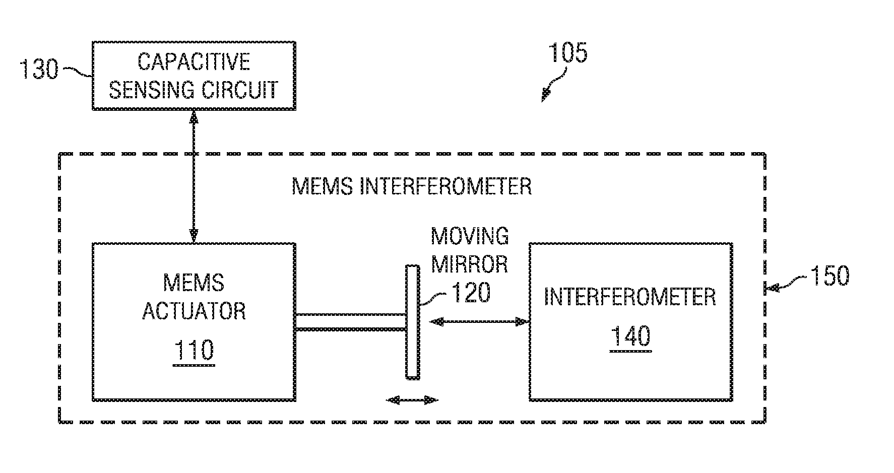
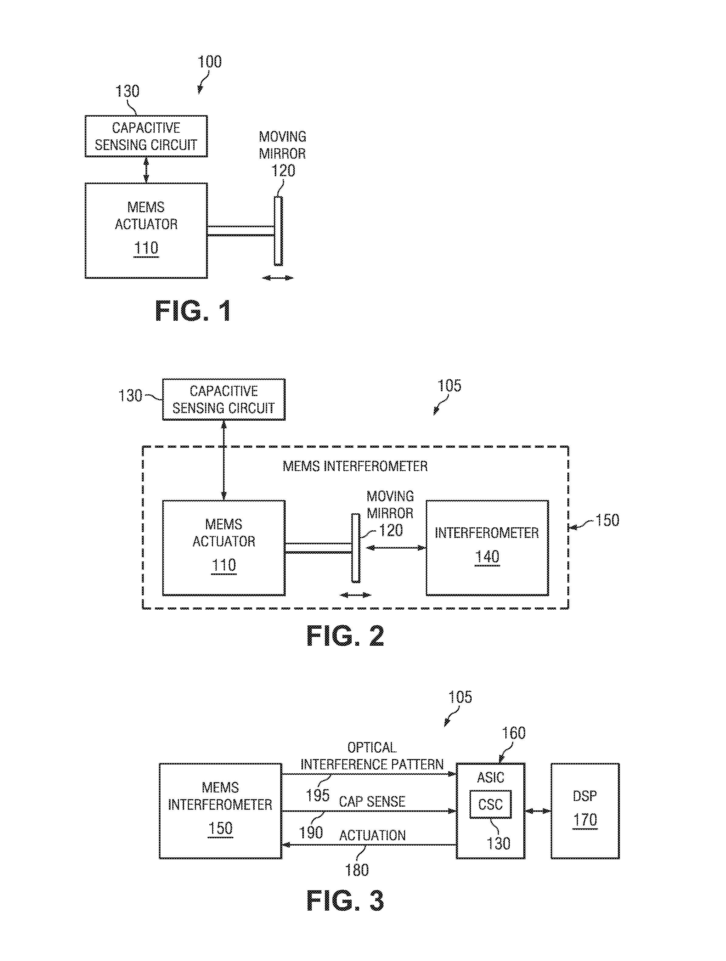
[0042]Referring now to FIG. 1, there is illustrated an exemplary MEMS apparatus 100, in accordance with embodiments of the present disclosure. The MEMS apparatus 100 includes a MEMS actuator 110 and a moveable mirror 120. The MEMS actuator 110 is an electrostatic actuator, such as a comb drive actuator, parallel plate actuator or other type of electrostatic actuator. The moveable mirror 120 is coupled to the MEMS actuator 110, such that motion of the MEMS actuator causes a displacement in the position of the moveable mirror 120.

[0043]In many MEMS appli...


PUM


Abstract

A Micro-Electro-Mechanical System (MEMS) apparatus provides for self-calibration of mirror positioning of a moveable mirror of an interferometer. At least one mirror in the MEMS apparatus includes a non-planar surface. The moveable mirror is coupled to a MEMS actuator having a variable capacitance. The MEMS apparatus includes a capacitive sensing circuit for determining the capacitance of the MEMS actuator at multiple reference positions of the moveable mirror corresponding to a center burst and one or more secondary bursts of an interferogram produced by the interferometer based on the non-planar surface. A calibration module uses the actuator capacitances at the reference positions to compensate for any drift in the capacitive sensing circuit.

Description

CROSS REFERENCE TO RELATED PATENTS[0001]The present U.S. Utility Patent Application claims priority pursuant to 35 U.S.C. §119(e) to the following U.S. Provisional Patent Application(s) which are hereby incorporated herein by reference in their entirety and made part of the present U.S. Utility Patent Application for all purposes:[0002]1. U.S. Provisional Application Ser. No. 62 / 269,866, entitled “Self Calibration for Mirror Positioning in Optical MEMS Interferometers,” (Attorney Docket No. SIWA-1007PROV3), filed Dec. 18, 2015.[0003]The present U.S. Utility Patent Application further claims priority pursuant to 35 U.S.C. §120, as a continuation-in-part (CIP), to the following U.S. Utility Patent Application which is hereby incorporated herein by reference in its entirety and made part of the present U.S. Utility Patent Application for all purposes:[0004]1. U.S. Utility application Ser. No. 14 / 165,997, entitled “Self Calibration for Mirror Positioning in Optical MEMS Interferometers,...

Claims


Application Information

Patent Timeline
IPC IPC(8): G01J3/453G02B26/08
CPCG01J3/4532G02B26/0841G01J3/4535G01J2003/2879G01B2290/35G01B7/08G01B9/02071G01B9/02068G01J3/45
Inventor MEDHAT, MOSTAFAMORTADA, BASSEMEI SHATER, AHMED OTHMANNAGY, MUHAMMEDGAD SEIF, MINASAADANY, BASSAM A.HAFEZ, AMR N.ANWAR, MOMEN
Owner SI WARE SYST INC
Why Eureka
Try Eureka