Method and apparatus for control of a steerable landing gear
- Summary
- Abstract
- Description
- Claims
- Application Information
AI Technical Summary
Benefits of technology
Problems solved by technology
Method used
Image

Examples
first embodiment
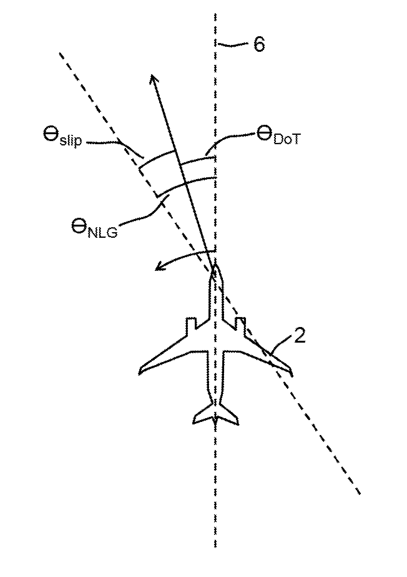
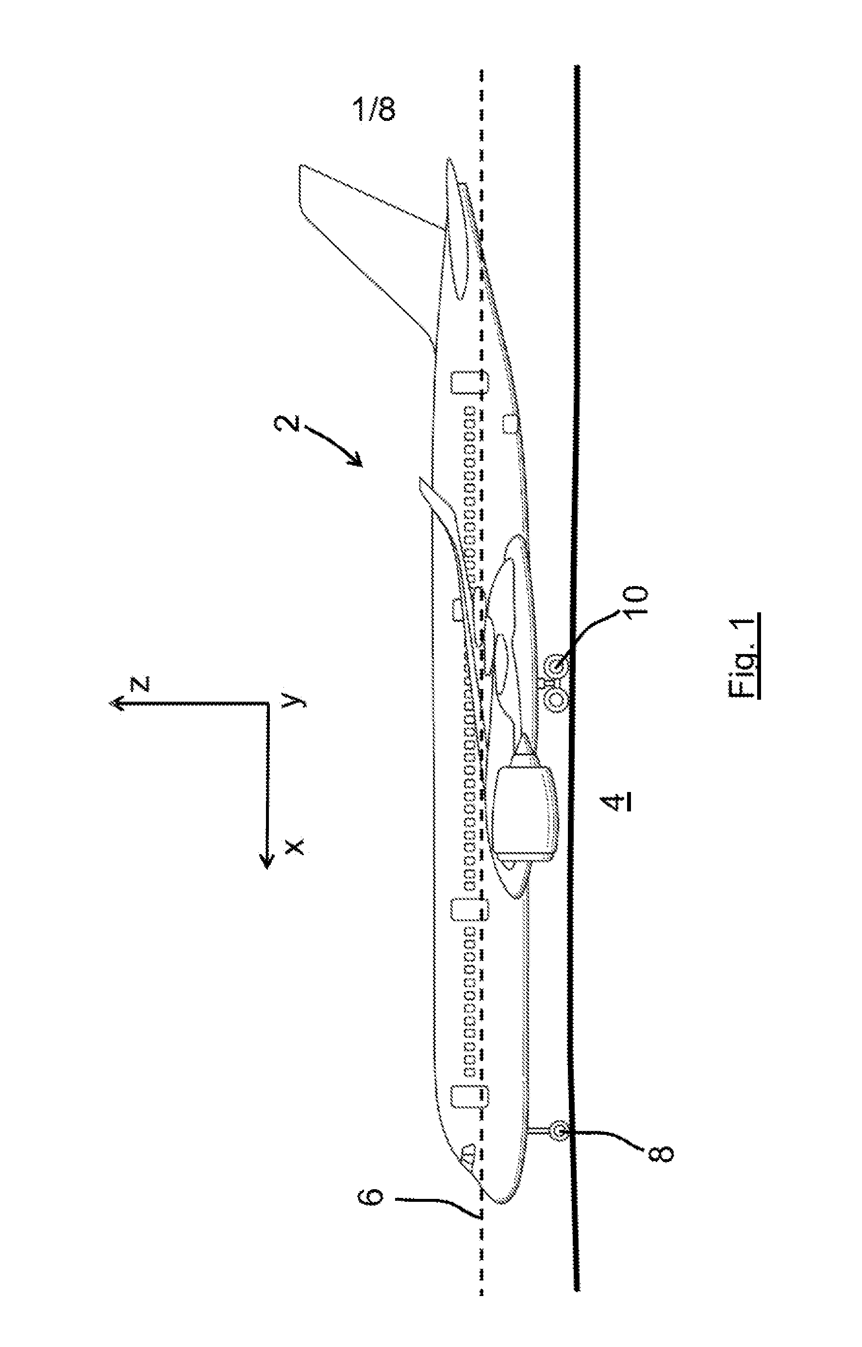
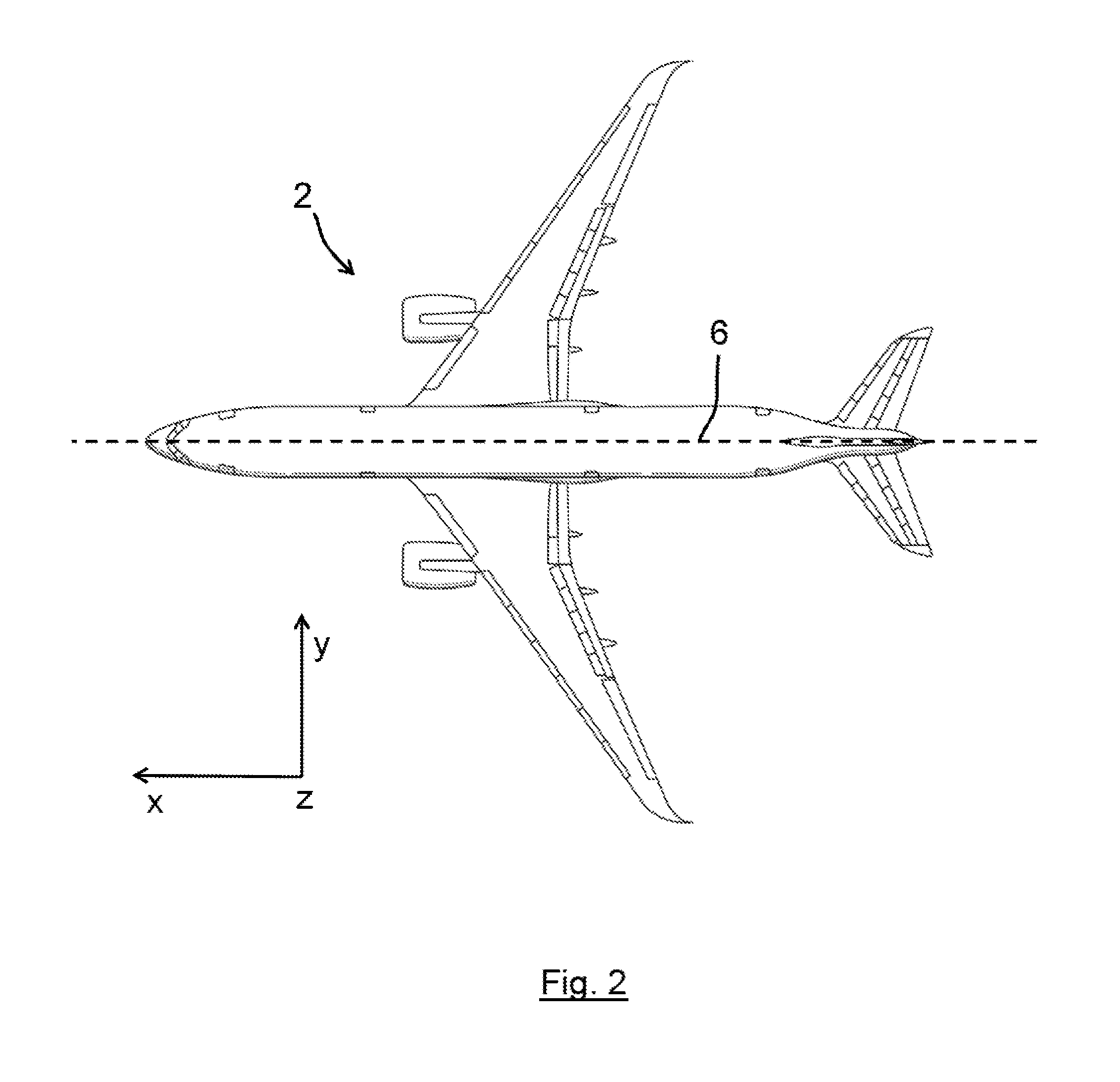
[0067]The first embodiment concerns a method of reducing vibration on an aircraft caused by the steering effected by a steerable nose landing gear. The aircraft is shown in FIGS. 1 and 2. FIG. 1 is a side view of the aircraft 2 travelling on a runway 4 and illustrates the longitudinal axis 6 of the aircraft and notional x-y- and z-axes in space, the x-axis being parallel to the longitudinal axis 6, the y-axis being horizontal and perpendicular to the x-axis and the z-axis being the vertical axis. FIG. 2 shows the same aircraft 2 and the same coordinate system (x-, y- and z-axes in space). The aircraft has a steerable nose landing gear (NLG 8) comprising wheels (one only of which being shown for the sake of clarity in the drawings) which may be steered in order to effect a turning motion on the aircraft when taxiing or otherwise moving on the ground. The aircraft also has a pair of main landing gear (MLG) assemblies, only one of which (MLG 10) is visible in FIG. 1.
[0068]When controll...
second embodiment
[0069]FIG. 5 shows a control flowchart illustrating the method and apparatus of the invention. Thus, a pilot using a hand wheel (or other form of tiller) 120 to order steering of the NLG 108. This order is processed by a unit 122 which converts the pilot's orders into an NLG steering angle demand. The (modified) demand is received at a slip-reduction control unit, represented by the parts that are within the box 130. A processing unit 132 receives the signal from the unit 122 together with a signal 140 representing the speed of the aircraft 102 and a signal 150 representing the current angle of steering of the NLG 108. If the values of the speed of the aircraft the angle of steering satisfy certain criteria (representing cases where the speed and steering angle are sufficiently low, with a very low value of one offsetting a relatively high value of the other), the processing unit 132 simply outputs the (modified) demand signal from the unit 122 without any change in the signal. This...
third embodiment
[0075]In a third embodiment, a slip parameter, namely the slip angle, is also used to control the steering rate. FIG. 6 shows the geometry of the aircraft and the way in which the slip angle can be derived. Thus, FIG. 6 shows the fixed distances between the NLG 8 and the MLG 10, the yaw about the centre of gravity 17 (close to the location of the MLG) and the speed of the aircraft as measured by a GPS unit 15. As shown in FIGS. 3 and 4, the slip angle is related to the NLG steering angle, θNLG, and the direction of travel angle, θDOT by:
θslip=θNLG−θDOT (Equation 1)
[0076]The angle of direction of travel, θDOT, at the NLG 8 can be calculated from measures of the aircraft velocity at the NLG. If the component of velocity in the x-direction (i.e. along the longitudinal axis) and the component of the NLG velocity in the y-direction (i.e. perpendicular to the longitudinal axis) are both known, the angle of direction of travel, θDOT can (see FIG. 7) be calculated from
tan (θDIT)=VNLGy / VNL...
PUM
 Abstract
Description
Claims
Application Information
 - Generate Ideas
- Intellectual Property
- Life Sciences
- Materials
- Tech Scout
- Unparalleled Data Quality
- Higher Quality Content
- 60% Fewer Hallucinations
Browse by: Latest US Patents, China's latest patents, Technical Efficacy Thesaurus, Application Domain, Technology Topic, Popular Technical Reports.
© 2025 PatSnap. All rights reserved.Legal|Privacy policy|Modern Slavery Act Transparency Statement|Sitemap|About US| Contact US: help@patsnap.com