Three level double voltage reducing type semi-bridge converter

A half-bridge inverter, three-level technology, used in electrical components, AC power input to DC power output, output power conversion devices and other directions, can solve the switching transient asynchronous, reduce circuit reliability, device Inconsistent parameters, etc., to achieve the effect of reducing the switching frequency of the device, simple control scheme, and reduced efficiency

Inactive Publication Date: 2007-07-25
NANJING UNIV OF AERONAUTICS & ASTRONAUTICS
View PDF0 Cites 15 Cited by
  • Summary
  • Abstract
  • Description
  • Claims
  • Application Information

AI Technical Summary

Problems solved by technology

Due to the limitation of device manufacturing technology, the withstand voltage of power semiconductor devices has a certain limit
In high-voltage converters, power tubes can be used in series, but due to inconsistencies in device parameters and asynchronous switching transients, it is difficult to achieve voltage equalization in steady-state and transient processes, resulting in overvoltage of individual power tubes and reducing circuit reliability

Method used


Image

  • Three level double voltage reducing type semi-bridge converter
  • Three level double voltage reducing type semi-bridge converter
  • Three level double voltage reducing type semi-bridge converter

Examples


Embodiment 1

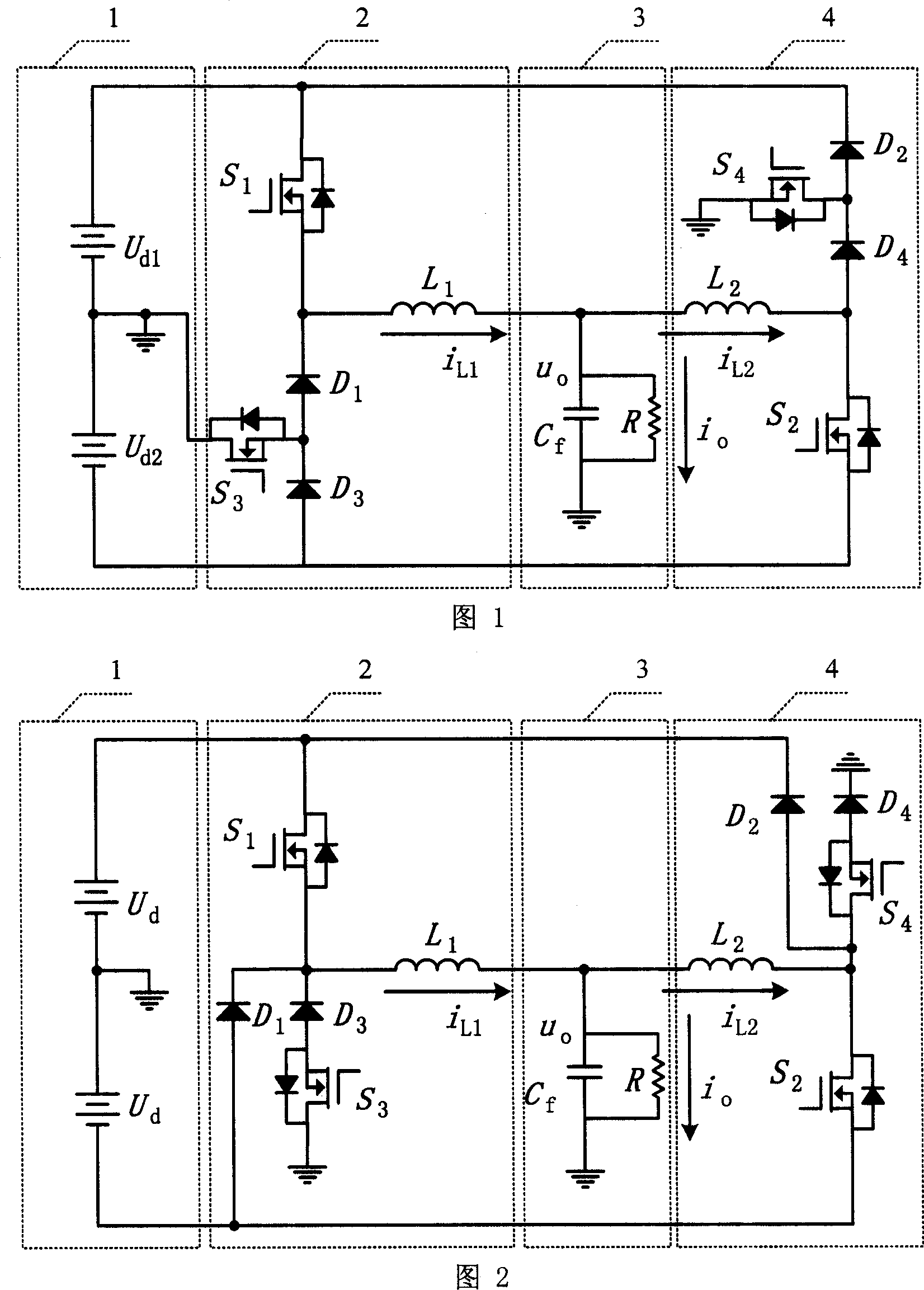
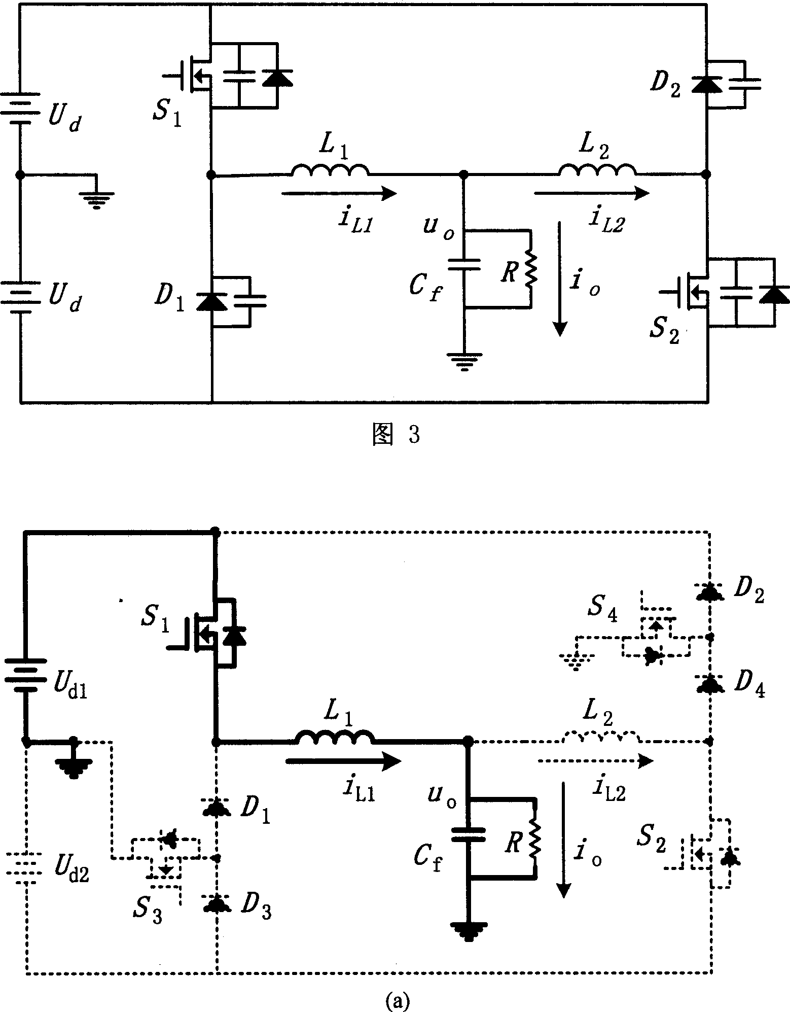
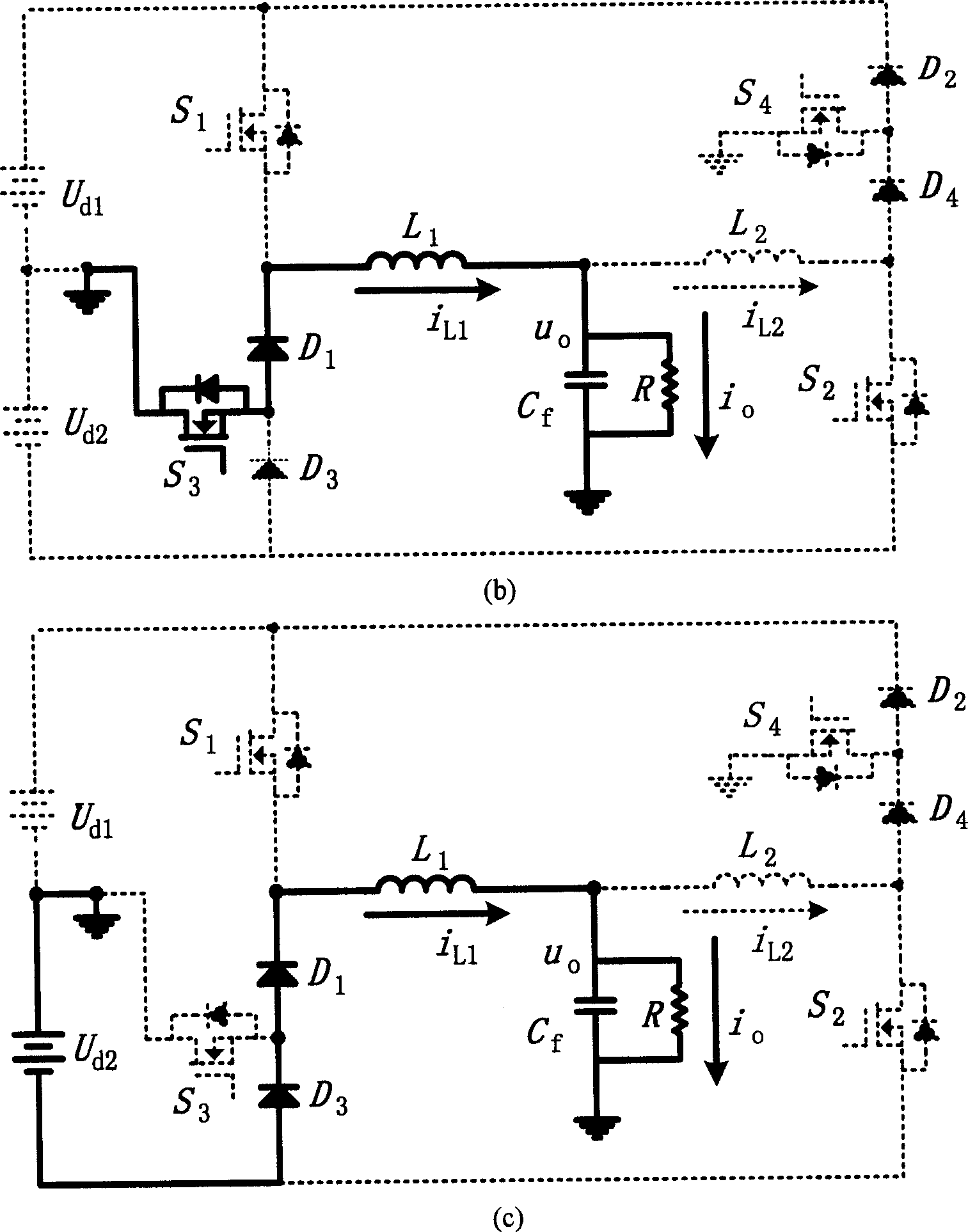
[0017] Embodiment 1: As shown in Figure 1, the three-level double-step-down half-bridge inverter of this embodiment includes a first three-level step-down circuit 2 and a second three-level step-down circuit 4, the first three In the level step-down circuit 2, the drain of the first power switch S1 is connected to the positive end of the external power supply Ud1, the source of the first power switch S1 is connected to the cathode of the first power diode D1, and the first power diode D1 The anode of the third power switch tube S3 is connected to the cathode of the third power diode D3, the anode of the third power diode D3 is connected to the negative end of the external power supply Ud2, the source of the third power switch tube S3 is connected between the power diodes D1 and D3, and the third power The drain of the switch tube S3 is grounded, and one end of the first inductor L1 is connected between the source of the first power switch tube S1 and the cathode of the first po...

Embodiment 2

[0018]Embodiment 2: As shown in Figure 2, the three-level double-step-down half-bridge inverter of this embodiment includes a first three-level step-down circuit 2 and a second three-level step-down circuit 4, the first three-level step-down circuit 4 In the three-level step-down circuit 2, the drain of the first power switch S1 is connected to the positive end of the external power supply Ud1, the source of the first power switch S1 is connected to the cathode of the third power diode D3, and the third power diode D3 The anode of D3 is connected to the source of the third power switch S3, the drain of the third power switch S3 is grounded, the cathode of the first power diode D1 is connected to the source of the first power switch S1 and the third power diode D3 Between the cathodes of the first power diode D1, the anode of the first power diode D1 is connected to the negative end of the external power supply Ud2, and one end of the first inductor L1 is connected to the cathod...


PUM


Abstract

The invention includes reduction voltage circuit of first and third electrical level, and reduction voltage circuit of second and third electrical level. Un the two circuits, one end of the power switch tube is connected to external electrical source; and the other end is connected to three levels combined switch composed of two power diodes and one power switch connected to each other. Advantages of the invention are: small content of harmonic wave in output voltage, reduced switch frequency and wastage of switch, no need of large capacitance on DC side, applicable to condition of high voltage and large power, no straight through issue of bridge arm, and no issue of backward recovery of diode in switch tube. Moreover, the invention possesses simple structure and control scheme, and good dynamic properties of the invention.

Description

1. Technical field [0001] The invention relates to an inverter, in particular to a double step-down half-bridge inverter. 2. Background technology [0002] Dual Buck Inverter (hereinafter referred to as DBI) is a new type of inverter topology that has emerged in recent years. Compared with the traditional bridge inverter, DBI has the unique advantages of high reliability without bridge arm direct connection and no reverse recovery problem of parasitic diode of switch tube; DBI working in half-cycle mode has no circulating current, which is to realize the inverter at the same time The high-frequency and high-efficiency provide a simple way, and it is a topological structure with great research value and development prospects. DBI and half-bridge inverters have many similarities, and they will be referred to as half-bridge inverters below. The half-bridge inverter needs an external positive and negative DC bus voltage, whose amplitude is more than twice the maximum output vo...

Claims


Application Information

Patent Timeline
Patent Type & Authority Applications(China)
IPC IPC(8): H02M7/5387
Inventor 洪峰蔡兆奇严仰光王慧贞
Owner NANJING UNIV OF AERONAUTICS & ASTRONAUTICS
Why Eureka
Try Eureka