Autostereoscopic display device

Inactive Publication Date: 2016-08-11
KONINKLJIJKE PHILIPS NV
View PDF5 Cites 25 Cited by
  • Summary
  • Abstract
  • Description
  • Claims
  • Application Information

AI Technical Summary

Benefits of technology

[0024]An alternative way to prevent cross talk is to use a barrier structure extending between the display and the view forming arrangement, to prevent light from the sub-array of pixels reaching the second optical elements and to prevent light from the other pixels reaching the first optical elemen

Problems solved by technology

However, one problem associated with the device is that the views projected by the lenticular sheet are separated by dark zones caused by “imaging” of the non-emitting black matrix which typically defines the display sub-pixel array.
Another problem is that the vertically aligned lens results in a reduction in resolution in the horizontal direction only, while the resolution in the

Method used


Image

  • Autostereoscopic display device
  • Autostereoscopic display device
  • Autostereoscopic display device

Examples


Embodiment Construction

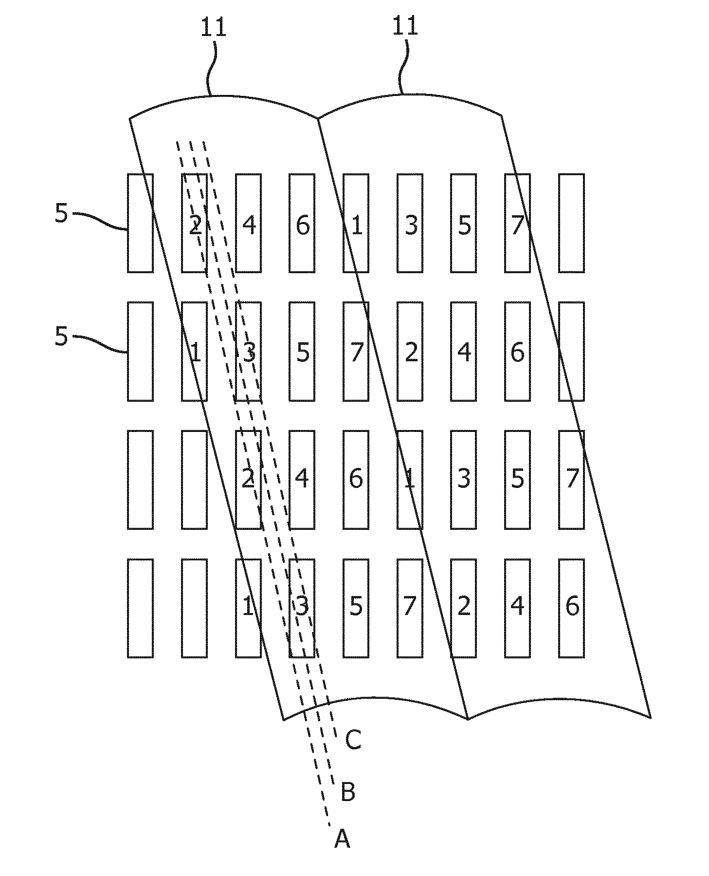
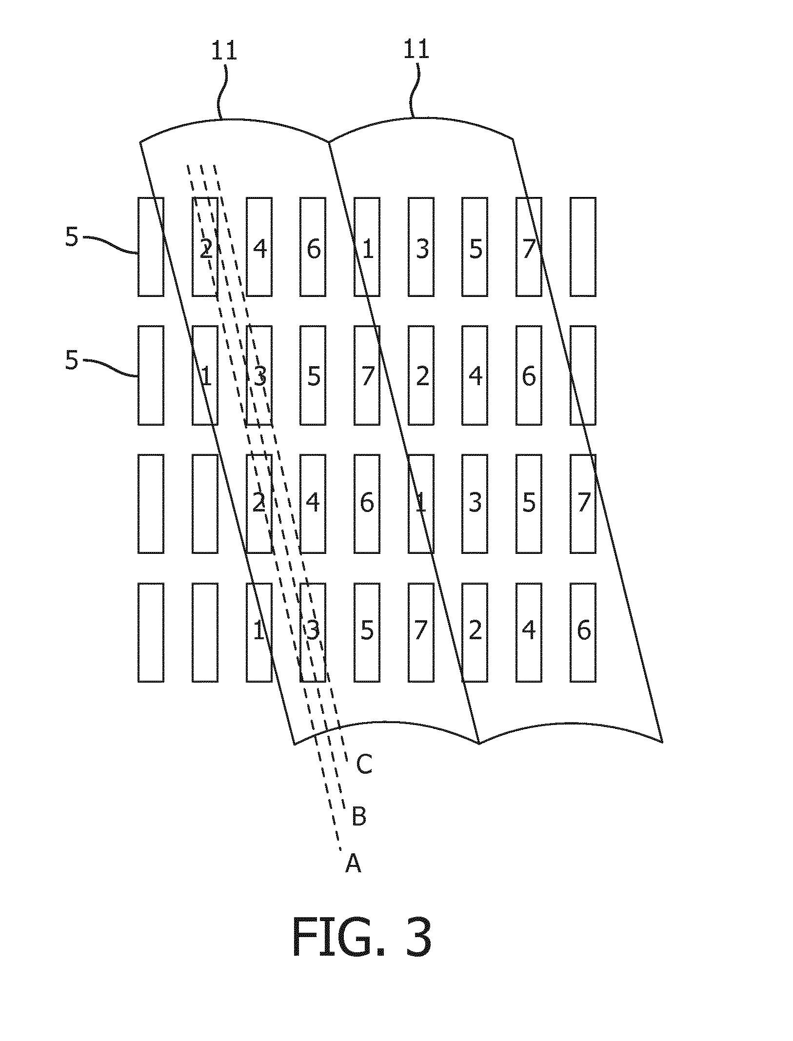
[0048]The invention provides an autostereoscopic display device in which a view forming arrangement comprises a first array of first optical elements associated with 3D pixels for generating 3D images, and a second array of second optical elements associated with other display pixels for generating 2D viewing images. In this way, an improved resolution 2D function is enabled without the need to make the display switchable between viewing modes.

[0049]Before describing the invention in detail, the configuration of a known autostereoscopic display will first be described.

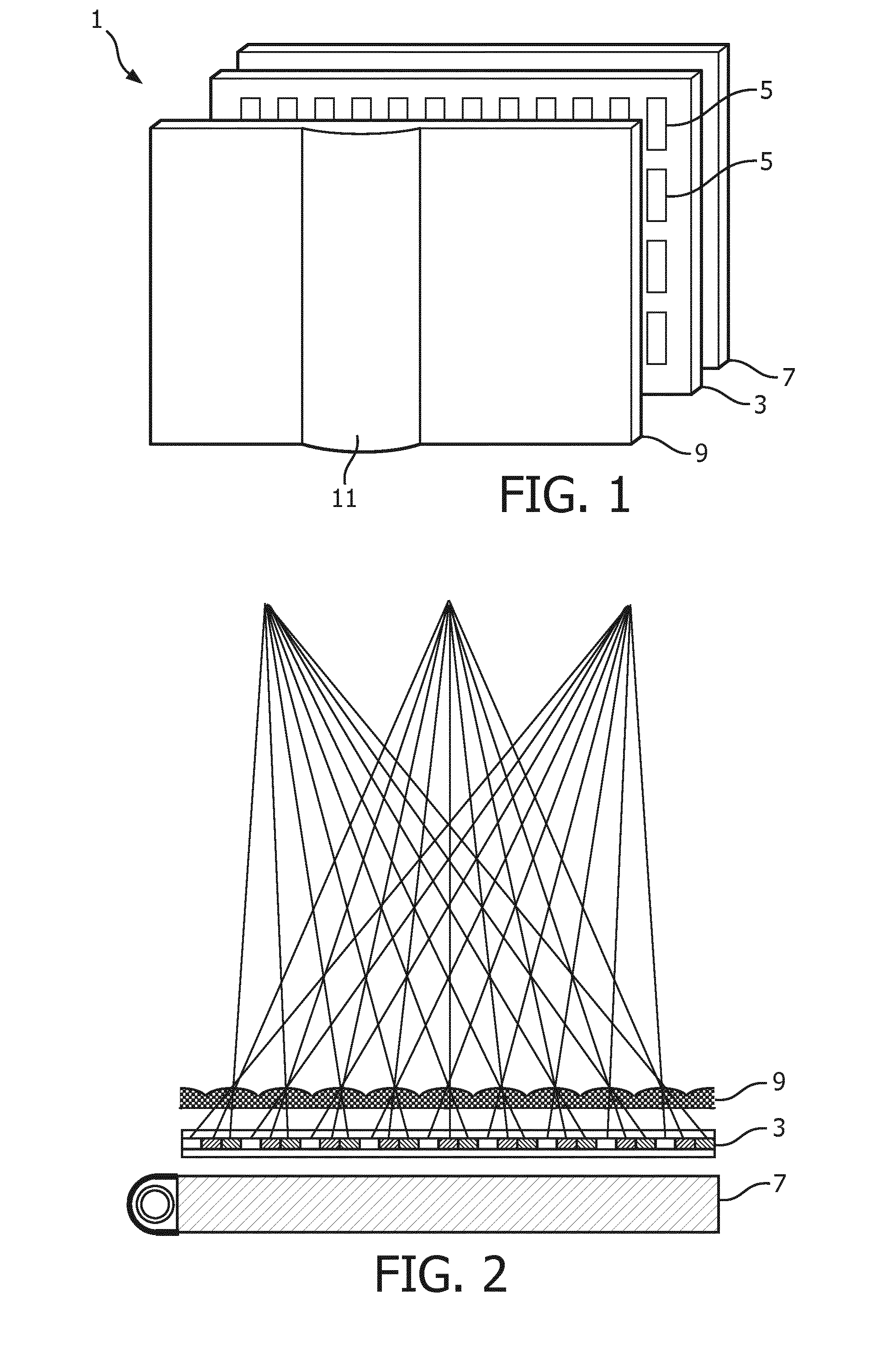
[0050]FIG. 1 is a schematic perspective view of a known multi-view autostereoscopic display device 1. The known device 1 comprises a liquid crystal display panel 3 of the active matrix type that acts as an image forming means to produce the display. The device can instead use OLED pixels.

[0051]The display panel 3 has an orthogonal array of display sub-pixels 5 arranged in rows and columns. For the sake of clarity, only...


PUM


Abstract

An autostereoscopic display device uses a view forming arrangement which comprises a first array of first optical elements associated with 3D pixels for generating 3D images, and a second array of second optical elements associated with other display pixels for generating 2D viewing images. In this way, an improved 2D resolution function is enabled without the need to make the display switchable between viewing modes.

Description

FIELD OF THE INVENTION[0001]This invention relates to an autostereoscopic display device which comprises a display panel having an array of display pixels, and an arrangement for directing different views to different physical locations.BACKGROUND OF THE INVENTION[0002]A known autostereoscopic display device comprises a two-dimensional liquid crystal display panel having a row and column array of display pixels acting as an image forming means to produce a display. An array of elongated lenses extending parallel to one another overlies the display pixel array and acts as a view forming means. These are known as “lenticular lenses”. As an alternative to these lenticular lenses, the lenses may be circular in a cross section parallel to the array or have another form e.g. an “elongated circle”. In the field of 3D displays such lenses are generally denoted “microlenses”. Outputs from the display pixels are projected through these microlenses or lenticular lenses, which function is to mo...

Claims


Application Information

Patent Timeline
IPC IPC(8): H04N13/04G02B27/26G02B27/22G02B30/25G02B30/29G02B30/30
CPCG02B27/2214H04N13/0404H04N13/0409G02B27/26H04N13/0452H04N13/0456H04N13/0415H04N13/317H04N13/361H04N13/305H04N13/31H04N13/356G02B30/29G02B30/30G02B30/27G03B35/26G02B30/25
Inventor KROON, BARTJOHNSON, MARK THOMASVDOVIN, OLEXANDR VALENTYNOVYCHVAN PUTTEN, EIBERT GERJAN
Owner KONINKLJIJKE PHILIPS NV
Why Eureka
Try Eureka