
Tools for use in observation wells

a technology for observation wells and tools, applied in the direction of measurement using nmr, detection using electromagnetic waves, construction, etc., to achieve the effect of improving the signal signal-to-noise ratio

Active Publication Date: 2016-08-18
SCHLUMBERGER TECH CORP
View PDF5 Cites 7 Cited by
  • Summary
  • Abstract
  • Description
  • Claims
  • Application Information

AI Technical Summary

Benefits of technology

The patent describes a way to monitor a region of a formation in a wellbore using a permanent monitoring tool. This tool can make measurements at different times and infer properties of the formation at different depths. Any changes in these properties can be detected, and decisions can be made based on those changes. The tool can be magnetic resonance or electromagnetic. The measurements can be stacked to improve accuracy. Different depths of investigation can be selected using different lengths of antenna arrays. The inferred properties can include saturation or resistivity. The tool can be used in observation, injector, or production wells, and can be run with conductive or non-conductive casing. Overall, this technology can help gather valuable information from wellbores and improve oil and gas exploration and production.

Problems solved by technology

Measurements are typically performed in an uncased portion of the wellbore because conventional conductive casing tends to limit the electromagnetic signal that can pass between the interior and exterior of a cased wellbore.
This is not necessarily an issue when a well is being drilled since measurements can be made prior to setting the casing, but presents a challenge should one wish to re-enter an existing cased wellbore to make updated measurements.

Method used


Image

  • Tools for use in observation wells
  • Tools for use in observation wells
  • Tools for use in observation wells

Examples


Embodiment Construction

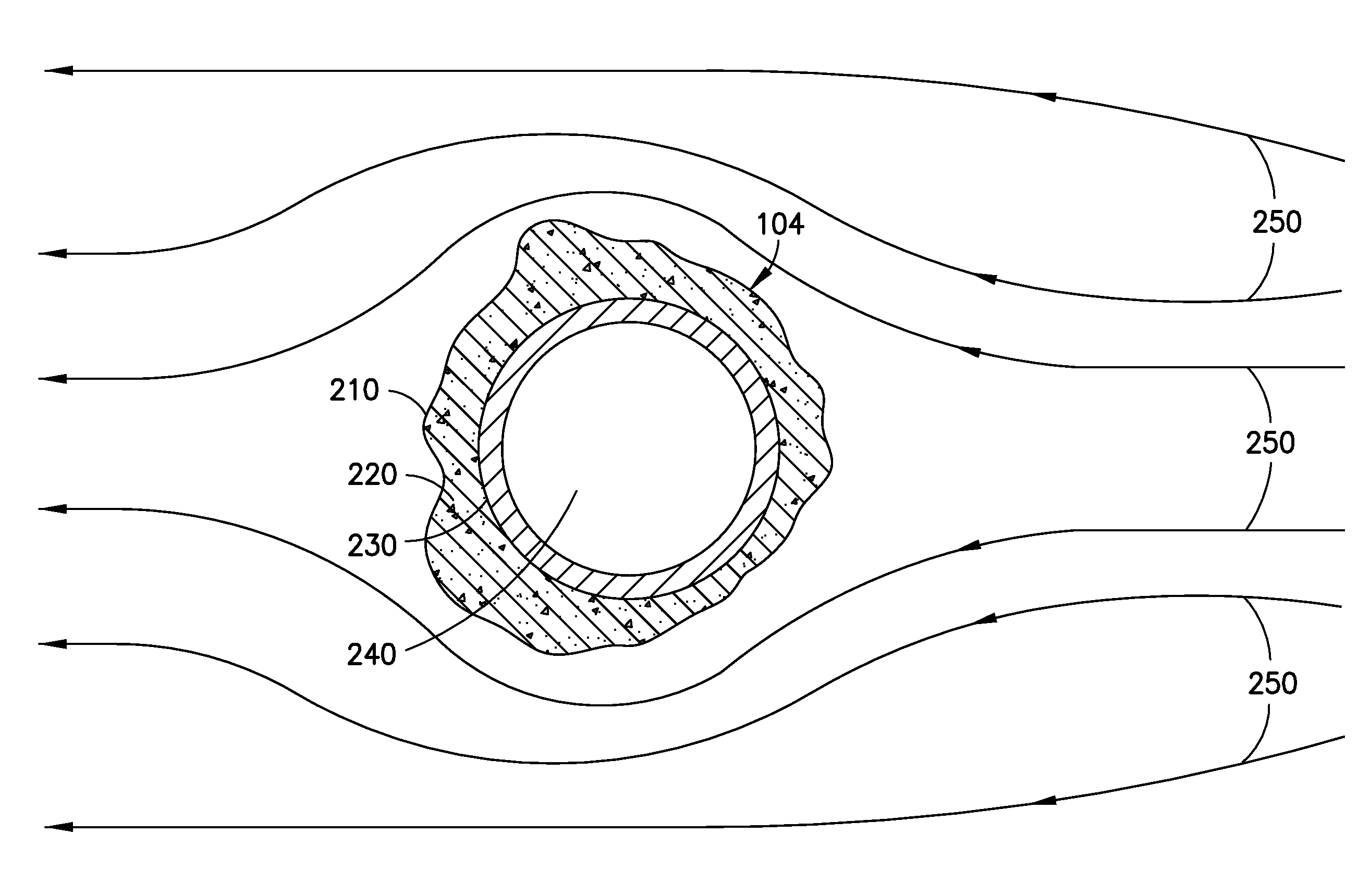
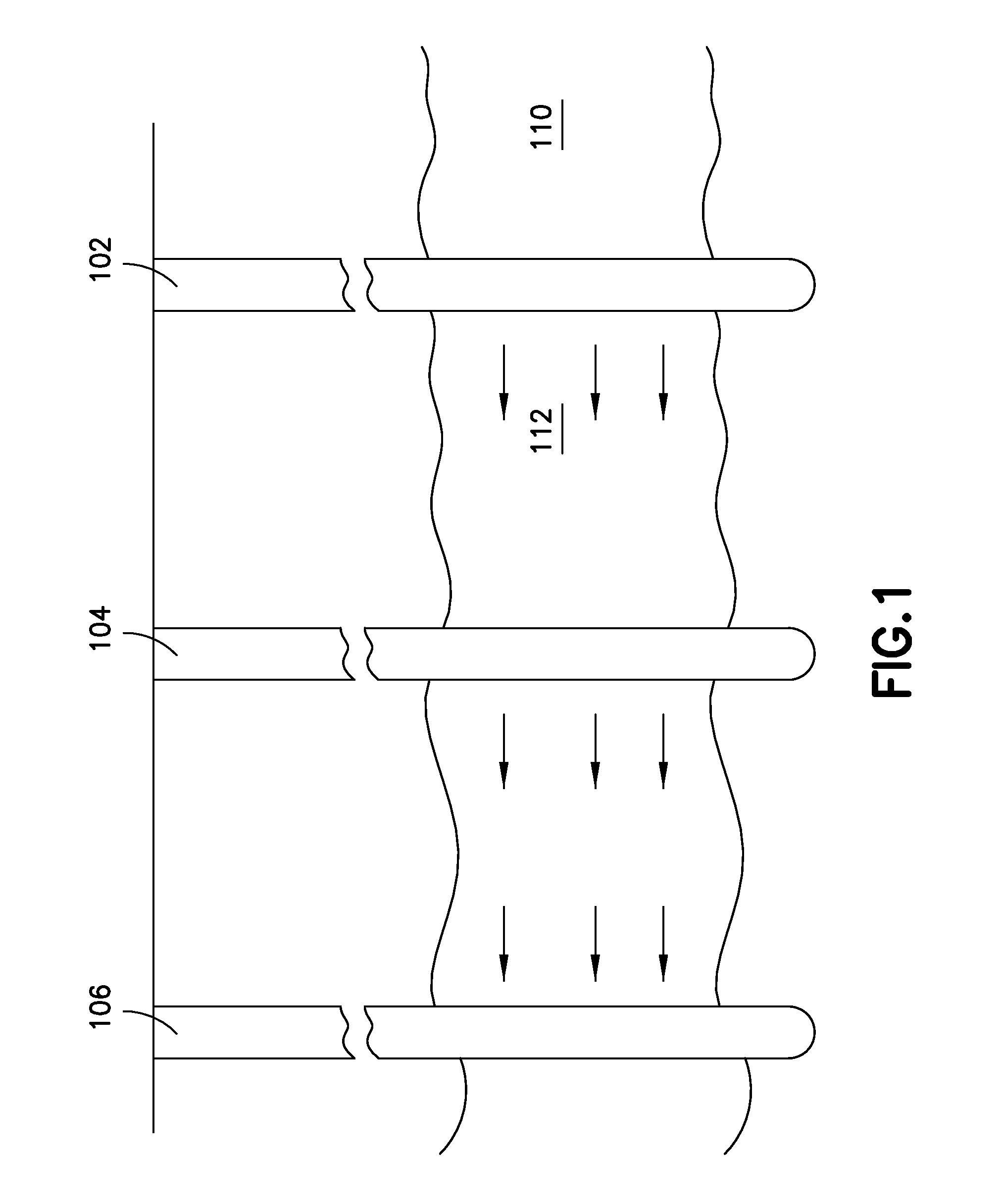
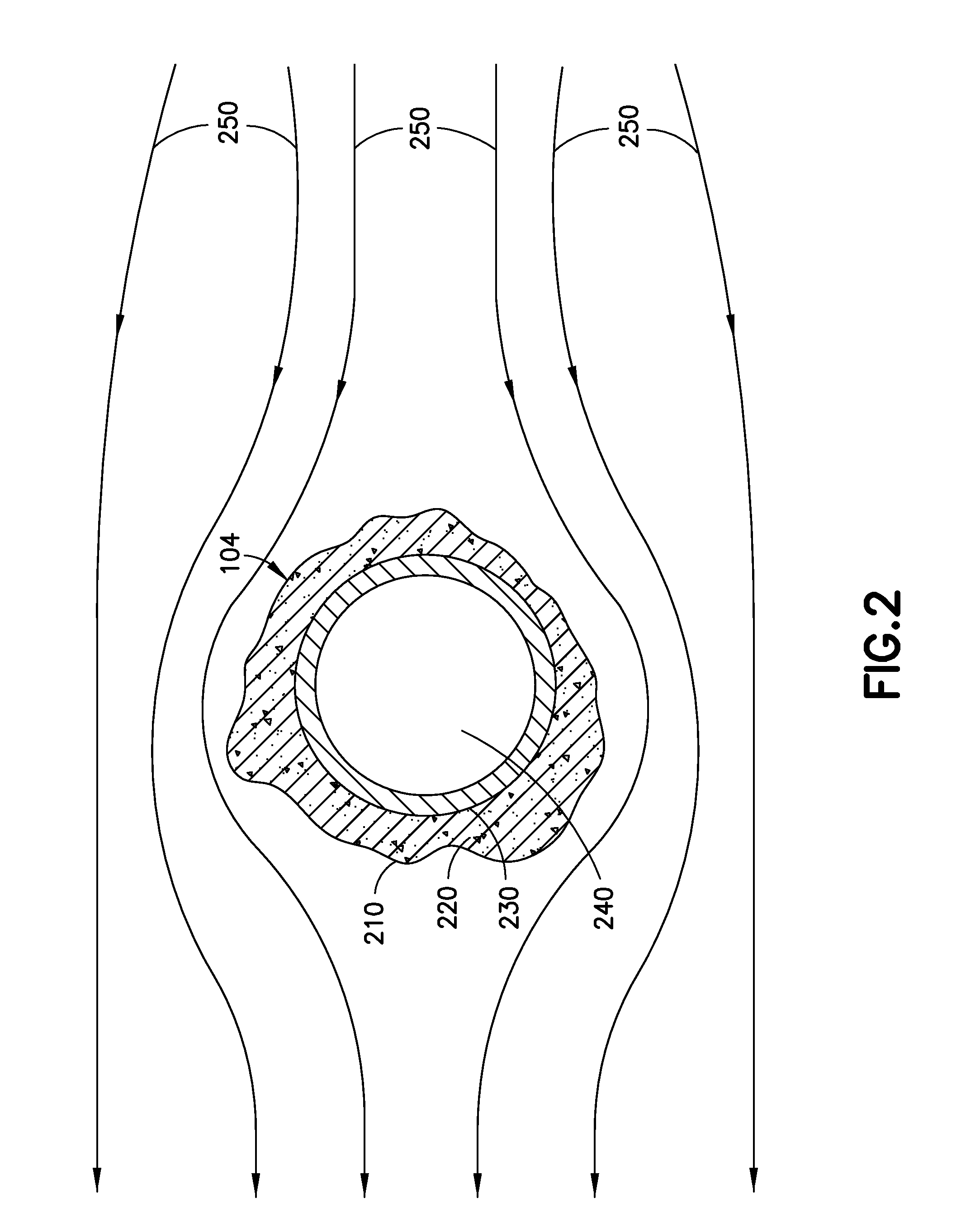
[0025]It is to be understood that the following disclosure provides many different embodiments, or examples, for implementing different features of various embodiments. Specific examples of components and arrangements are described below to simplify the present disclosure. These are, of course, merely examples and are not intended to be limiting. In addition, the present disclosure may repeat reference numerals and / or letters in the various examples. This repetition is for the purpose of simplicity and clarity and does not in itself dictate a relationship between the various embodiments and / or configurations discussed. Moreover, the formation of a first feature over or on a second feature in the description that follows may include embodiments in which the first and second features are formed in direct contact, and may also include embodiments in which additional features may be formed interposing the first and second features, such that the first and second features may not be in d...


PUM


Abstract

A permanent monitoring tool is provided and disposed in a wellbore. Measurements are made at different times using the permanent monitoring tool on a region of a formation penetrated by the wellbore. One or more properties of the formation are inferred at one or more depths of investigation within the region using the measurements. Any changes in the one or more inferred formation properties are determined and one or more reservoir management decisions are made based on the determined changes. The well may be an observation well, an injector well, or a production well. The permanent monitoring tool may be a magnetic resonance tool or an electromagnetic tool. The measurements may be stacked to improve the signal-to-noise ratio of the signal. Different depths of investigation may be selected using antenna arrays of different lengths. The inferred properties may be saturation or resistivity. Conductive or non-conductive casing may be used.

Description

CROSS-REFERENCE TO RELATED APPLICATIONS[0001]This application claims, under 35 U.S.C. §119, priority to and the benefit of U.S. Provisional Patent Application No. 61 / 886,812, filed Oct. 4, 2013.BACKGROUND OF THE DISCLOSURE[0002]Logging tools have long been used in wellbores to make, for example, formation evaluation measurements to infer properties of the formations surrounding the borehole and the fluids in the formations. Common logging tools include electromagnetic tools, nuclear tools, and nuclear magnetic resonance (NMR) tools, though various other tool types are also used.[0003]Early logging tools were run into a wellbore on a wireline cable, after the wellbore had been drilled. Modern versions of such wireline tools are still used extensively. However, the need for information while drilling the borehole gave rise to measurement-while-drilling (MWD) tools and logging-while-drilling (LWD) tools. MWD tools typically provide drilling parameter information such as weight on the b...

Claims


Application Information

Patent Timeline
IPC IPC(8): G01V3/32G01R33/50G01V3/30
CPCE21B47/0905G01R33/50G01V3/32G01V3/30E21B47/092
Inventor VALORI, ANDREABADRI, MOHAMMEDTAHERIAN, REZA
Owner SCHLUMBERGER TECH CORP
Learn More