Diagnostic Device And Method For Monitoring The Operation Of A Control Loop

Active Publication Date: 2016-08-18
SIEMENS AG
View PDF3 Cites 0 Cited by
  • Summary
  • Abstract
  • Description
  • Claims
  • Application Information

AI Technical Summary

Benefits of technology

The present invention provides a method for monitoring control loops in complex systems with multiple controls. This allows for the non-invasive diagnosis of subordinate control loops, such as in cascade or ratio control systems. The method uses only the data from the regular process mode and does not interrupt operation of the automated system. It also provides a clear and easily understandable evaluation of the status of the control loop by displaying characteristic numbers based on the scatter of the setpoint data. This method can also be used for monitoring slave controllers in cascade or ratio control systems. Overall, this invention improves the monitoring and diagnosis of control loops in complex systems.

Problems solved by technology

If, on the other hand, the variance of the actual value is greater than that of the setpoint, the slave controller automatically disrupts the control loop, i.e. it is likely incorrectly set.
Because with cascade control systems system operators tend to pay more attention to the master controller than to the slave controller, and since an irregular response on the part of the slave control loop is not necessarily evident on the master control loop—particularly as the slave control loop is generally configured to be much quicker than the master control loop—there has heretofore been a serious risk that deteriorations in the slave control loop would remain unnoticed.
Even if an irregular response on the part of the slave control loop does not have a significant impact on the final controlled variable, it could still result in drawbacks, such for example as more rapid wear of an actuating element or higher energy consumption since, in a cascade control system, the actuating element for the final controlled variable is controlled directly by the slave controller and not by the master controller.
If, on the other hand, the variance of the actual value is greater than that of the setpoint, the slave controller automatically disrupts the control loop, i.e. it is probably incorrectly set.

Method used


Image

  • Diagnostic Device And Method For Monitoring The Operation Of A Control Loop
  • Diagnostic Device And Method For Monitoring The Operation Of A Control Loop
  • Diagnostic Device And Method For Monitoring The Operation Of A Control Loop

Examples


Embodiment Construction

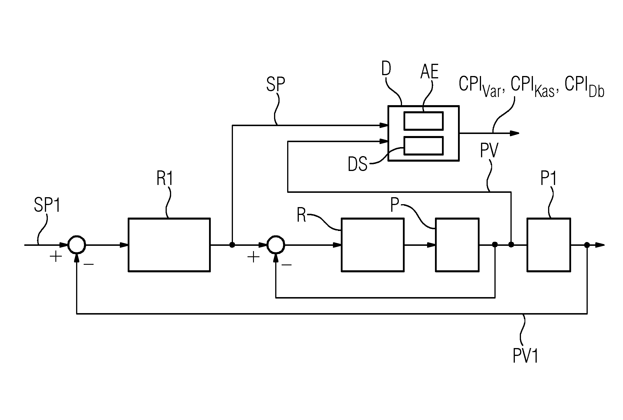
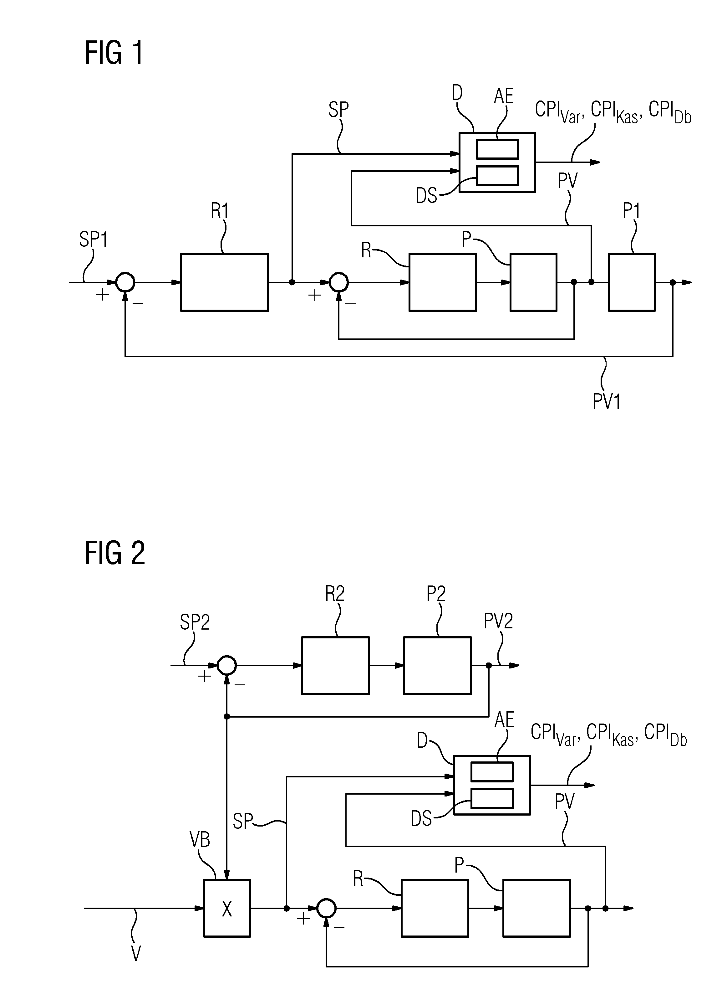
[0022]FIGS. 1 and 2 depict, by way of example, control loops in meshed structure implemented in, respectively, a cascade control system and a ratio control system. A control loop to be monitored includes a controller R and a process P; the controller R is referred to as a slave controller in a cascade control system and as a ratio controller in a ratio control system. In a cascade control system such as that represented by FIG. 1, the controller R obtains its setpoint SP from a master controller R1, which is a component of an external control loop for controlling a controlled variable PV1 of a process P1. In the following description, the controlled variable PV of the process P is also referred to as the actual value. In a ratio control system such as that represented by FIG. 2, the setpoint SP is provided by a ratio module VB, which calculates the setpoint as the ratio of an actual value PV2 of another control loop and a ratio value V. The other control loop, the actual value PV2 o...


PUM


Abstract

A diagnostic device and method for monitoring the operation of a slave or ratio control loop in a meshed control structure of an automation system. The diagnostic device includes an evaluation device and a data memory for storing sequences of setpoint data and actual value data. The evaluation device determines a first dimension for the scatter of the actual-value data and a second dimension for the scatter of the setpoint data. A characteristic number (CPIVar, CPIKas) for evaluating control quality is determined and / or displayed as a function of the ratio of the first dimension to the second dimension to enable an operator to evaluate the control loop status, permitting automated control loop evaluation of a fluctuating setpoint.

Description

BACKGROUND OF THE INVENTION[0001]1. Field of the Invention[0002]The invention relates to a diagnostic device and method for monitoring the operation of a control loop of an automation system.[0003]2. Background of the Invention[0004]The maintenance and servicing of automation systems can be improved if subsystems or components are monitored to ensure that they are functioning correctly. In the event of reduced operational performance, it is possible to intervene selectively at the appropriate point of the system with maintenance, servicing or fault-clearance measures. Components of automation systems are typically interconnected in control loops. Identifying of reduced capacity of individual control loops to enable timely and selective intervention at the appropriate point of the system with measures for servicing or controller optimization would be enhanced by permanent and automatic monitoring of the control quality of control loops in the system.[0005]A diagnostic method for moni...

Claims


Application Information

Patent Timeline
IPC IPC(8): G05B19/406
CPCG05B23/024G05B2219/42001G05B19/406G05B23/0243G05B2219/24024
Inventor HEILER, PATRICKPFEIFFER, BERND-MARKUS
Owner SIEMENS AG
Why Eureka
Try Eureka