Marker image processing system

a processing system and image technology, applied in image enhancement, image analysis, instruments, etc., can solve the problems of undesired increase in measurement error of markers, difficult to securely determine whether or not marker measurement values are true values, etc., to achieve accurate and secure posture estimation, low cost, and easy modification

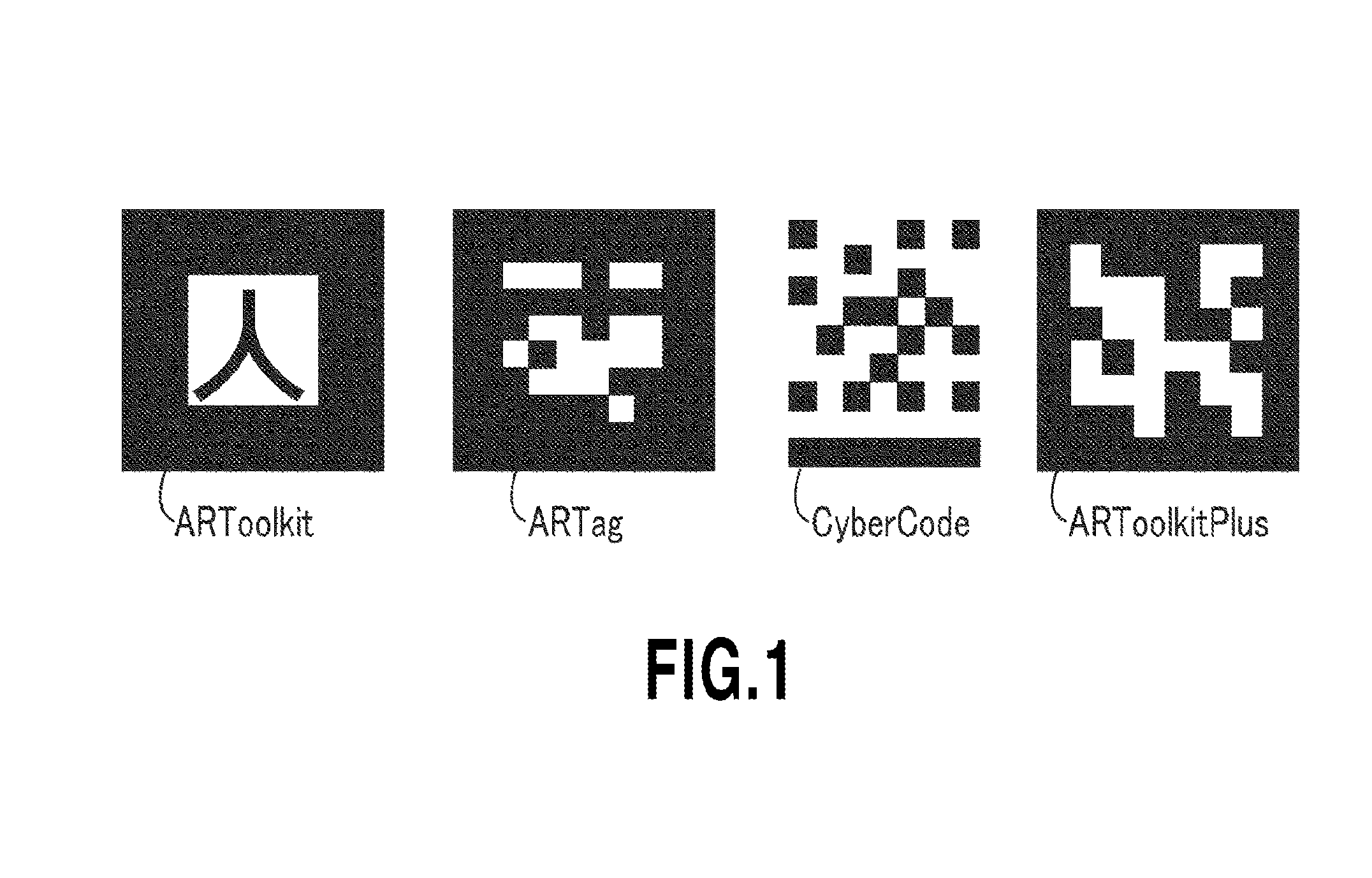
Active Publication Date: 2016-08-18
NAT INST OF ADVANCED IND SCI & TECH
View PDF2 Cites 19 Cited by
  • Summary
  • Abstract
  • Description
  • Claims
  • Application Information

AI Technical Summary

Benefits of technology

[0019]According to the present invention, by merely locating one three-dimensional indicator having a predetermined height at a predetermined position of a marker having a plane indicator, whether an estimated posture is appropriate or not can be determined. When a false estimation is determined, then the data of the posture of the camera relative to an already-calculated marker can be easily modified by converting the data based on a fixed rule. Thus, accurate and secure posture estimation can be achieved with a low cost without being disturbed by other three-dimensional indicators.

Problems solved by technology

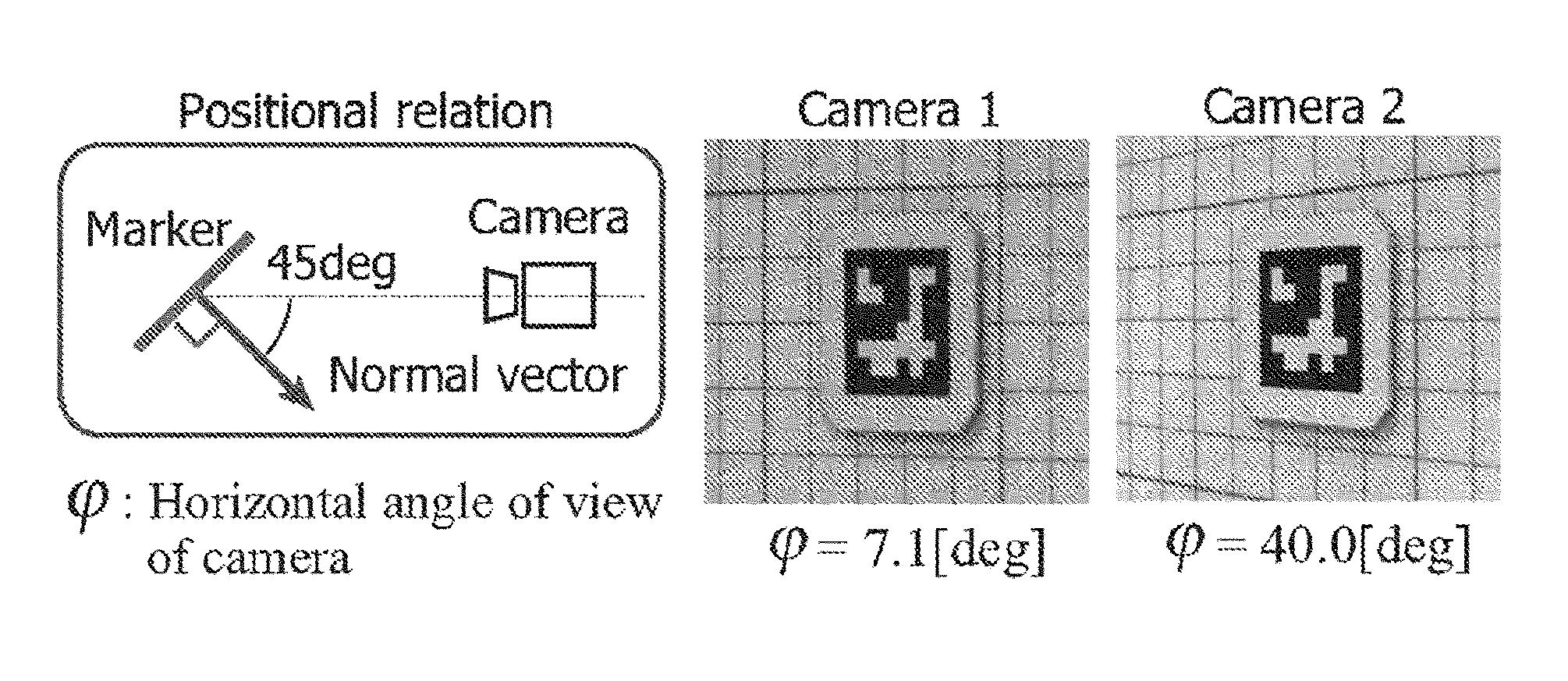
However, at a position in the vicinity of where the marker faces the camera, the marker undesirably has an increased measurement error.
Furthermore, even when the camera can reduce the dispersion of marker measurement values by using a filter (e.g., an average filter, a Kalman filter, or a particle filter) or a measurement history, it has been difficult to securely determine whether or not the marker measurement values are a true value.

Method used


Image

  • Marker image processing system
  • Marker image processing system
  • Marker image processing system

Examples


embodiment

[0034]First, a marker used in this embodiment will be described. As shown in FIG. 6, a flat plate-type marker is configured so that a square having an outer frame of 20 mm includes therein, at the center thereof, a white circle 1 having a diameter of 12 mm and white circles 2 having a diameter of 3 mm provided at the same positions on the diagonal lines from the respective vertexes of the outer frame and the remaining part is configured by a black square. In this embodiment, at a position separated by 5 mm from the bottom side of the outer frame of this flat plate-type marker, a three-dimensional indicator 3 is adhered that is composed of a cylindrical body having an outer diameter of 4.9 mm and a height of 3.2 mm. This three-dimensional indicator 3 has, on the upper face thereof, a white circle part having a diameter of 2.2 mm at the center to thereby form a marker having a black-colored outer circumference.

[0035]First, by a method similar to the conventional one, the white circles...


PUM


Abstract

The marker has thereon one three-dimensional indicator 3. Based on the location and height of the three-dimensional indicator 3 relative to the plane indicator 2 as well as the estimated position of the camera relative to the marker, the center positions of the upper face and the lower face of the three-dimensional indicator 3 on the image of the camera are estimated. The estimated center position of the upper face of the three-dimensional indicator 3 is compared with that detected from the image. When the error between them has a value equal to or higher than a predetermined value, based on the posture estimated, a rotational transformation is carried out.

Description

TECHNICAL FIELD[0001]The present invention relates to a marker image processing system to extract various pieces of information by subjecting a marker to an image processing.BACKGROUND ART[0002]Such a marker is used in the field of AR (Augmented Reality), the measurement field of a local portion, and the robotics field in order to allow a camera to recognize the position or posture of an object. Generally, a flat plate-type marker including a plane pattern that can be adhered to an object as a target has been widely used.[0003]For example, in order to realize the practical use of service robots in the future, a marker is an indispensable element to structure a system to support a secure autonomous operation by a service robot. A typical marker includes a black square frame as well as a two-dimensional pattern and a code printed therein. The marker is recognized by a camera so that the relative position and posture to the marker can be recognized and the position and posture of the o...

Claims


Application Information

Patent Timeline
Patent Type & Authority Applications(United States)
IPC IPC(8): G06T7/00G01D5/26G06T7/60
CPCG06T7/0044G06T2207/30204G06T2207/30244G06T2200/04G06T7/004G06T7/60G01D5/26G06T7/70G06T7/74
Inventor TANAKA, HIDEYUKI
Owner NAT INST OF ADVANCED IND SCI & TECH
Why Eureka
Try Eureka