
Pixel driver circuit, display panel and driving method therefor

a technology of pixel driver and display panel, which is applied in the direction of electrical equipment, semiconductor devices, instruments, etc., can solve the problems of deterioration of panel uniformity, difficult control of pixels brightness to be within the range of 1% in the amoled display panel, and non-uniform so as to improve the uniformity and stability of the brightness of the display panel

Active Publication Date: 2016-08-18
TCL CHINA STAR OPTOELECTRONICS TECH CO LTD
View PDF5 Cites 13 Cited by
  • Summary
  • Abstract
  • Description
  • Claims
  • Application Information

AI Technical Summary

Benefits of technology

The present invention aims to design a pixel driver circuit and a compensation method for an AMOLED display panel. The circuit and method aim to improve the uniformity and stability of the brightness of the display panel. By compensating for the shift of the threshold voltage of the AMOLED, the invention eliminates the impact of voltage on current and ensures consistent brightness across the entire panel. This results in a more uniform and stable display of light from the panel.

Problems solved by technology

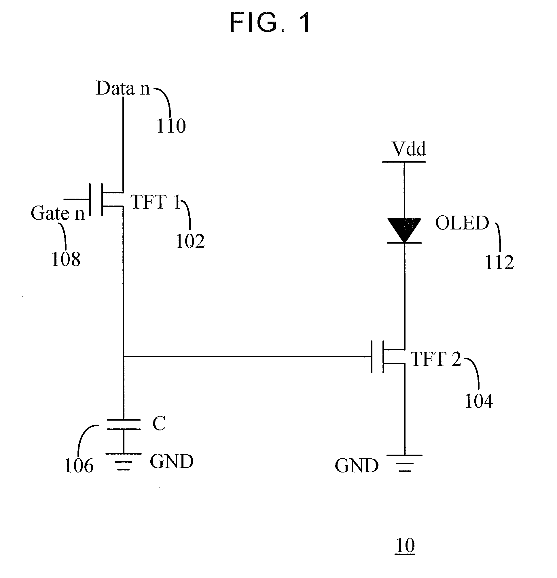
In an active-matrix organic light-emitting diode (AMOLED) display panel, various effects may result in the deterioration of the uniformity of the panel.
Since most integrated circuits transmit voltage signals rather than current signals, it is difficult to control the brightness of the pixels to be within the range of ±1% in the AMOLED display panel.
Actually, since the threshold voltages and mobility of transistors in the AMOLED display panel shift over time, these shortcomings may cause the non-uniformity of the brightness of the display panel.

Method used


Image

  • Pixel driver circuit, display panel and driving method therefor
  • Pixel driver circuit, display panel and driving method therefor
  • Pixel driver circuit, display panel and driving method therefor

Examples


Embodiment Construction

[0024]The descriptions of the following embodiments refer to the attached drawings which are utilized to exemplify specific embodiments. Directional terms mentioned in the present invention, such as “top” and “down”, “front”, “rear”, “left”, “right”, “inside”, “outside”, “side” and so on are only directions with respect to the attached drawings. Therefore, the used directional terms are utilized to explain and understand the present invention but not to limit the present invention. In different drawings, the same reference numerals refer to like parts throughout the drawings.

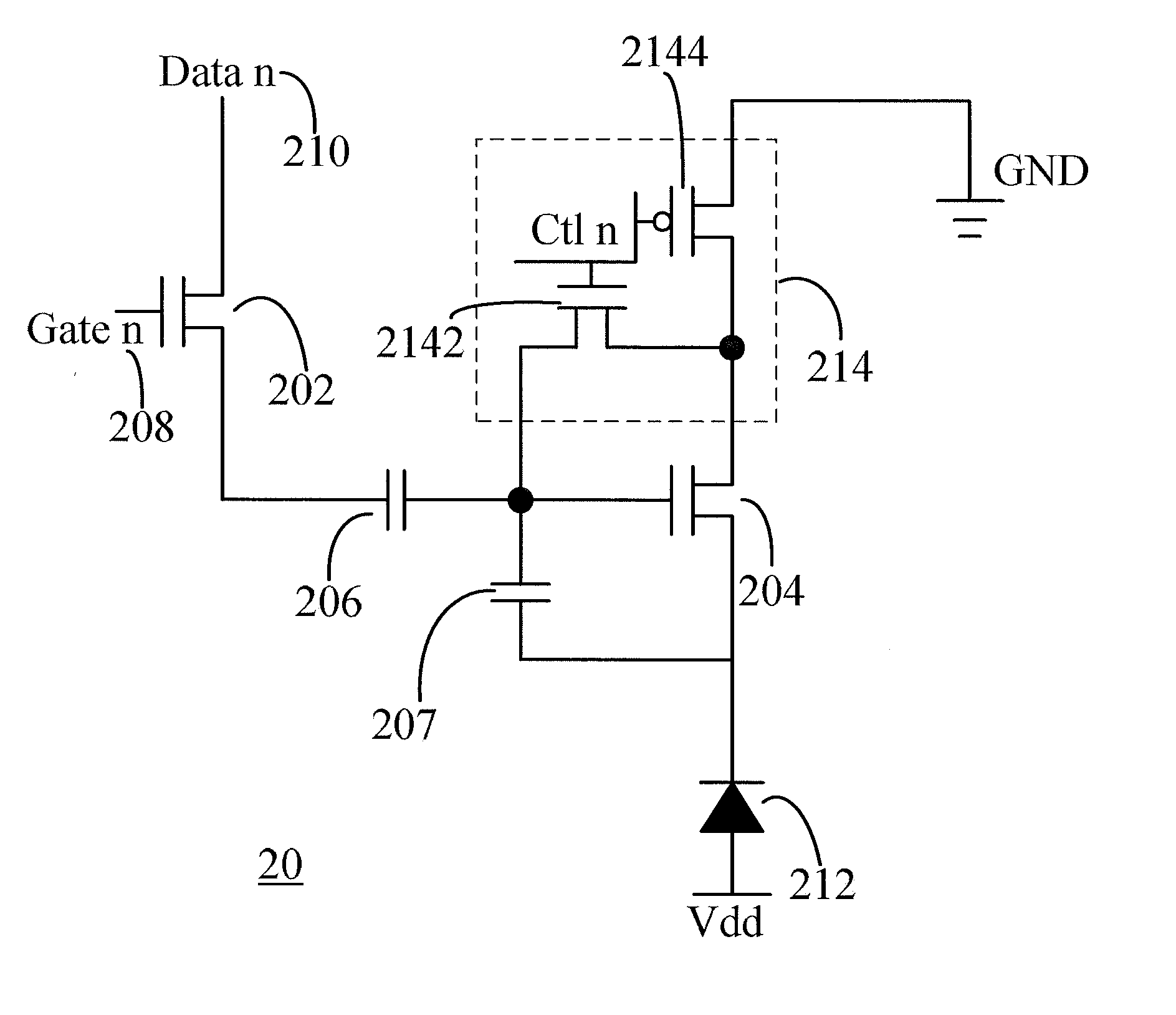
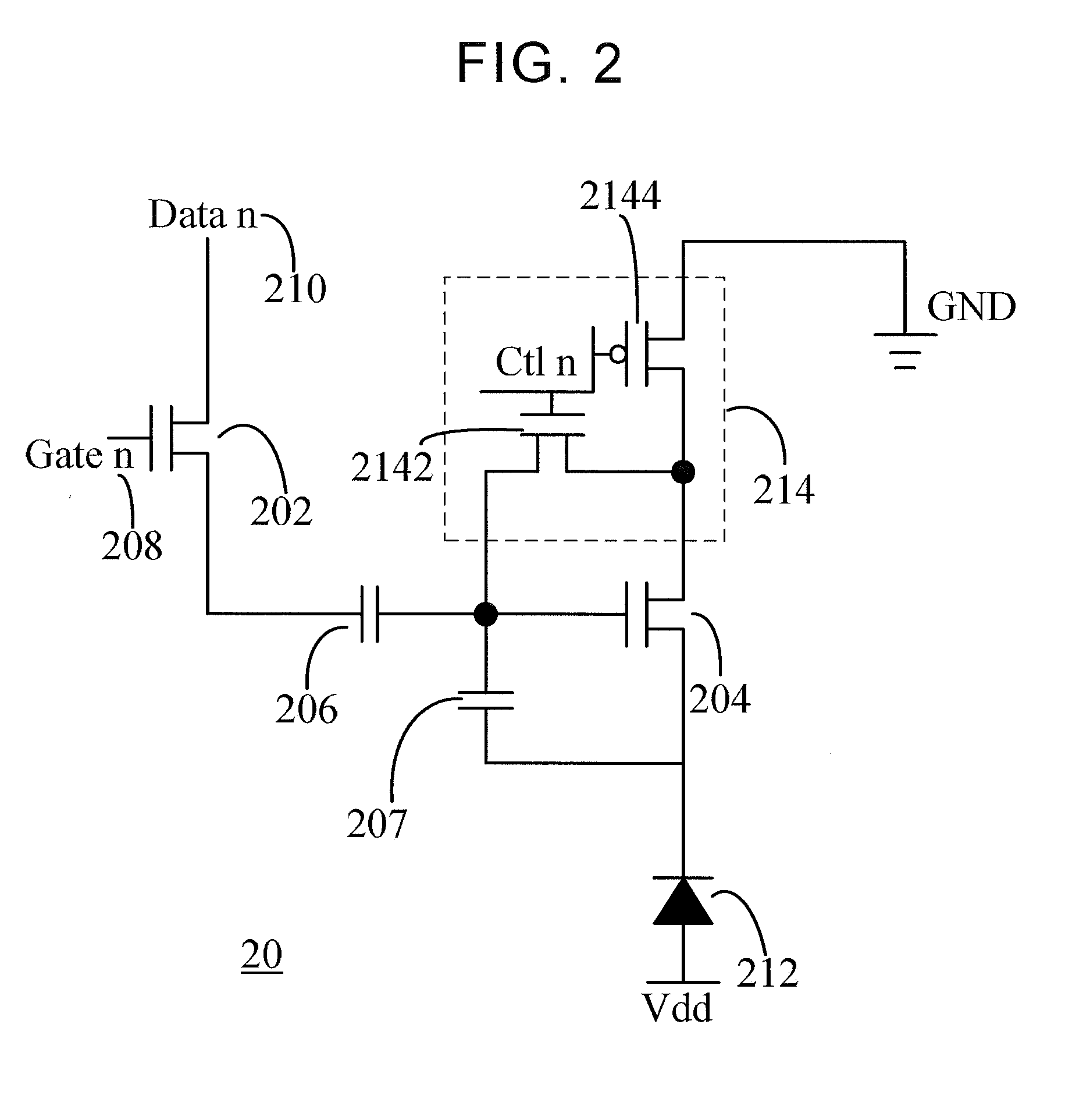
[0025]FIG. 2 depicts a pixel driver circuit diagram illustrating an AMOLED display panel according to one preferred embodiment of the present invention. A pixel driver circuit is formed on an array substrate, and a plurality of data lines and gate lines are disposed on the array substrate. The plurality of data lines and gate lines define a plurality of pixel driver circuits. In addition, the array substrate fur...


PUM

PropertyMeasurementUnit
threshold voltageaaaaaaaaaa
voltageaaaaaaaaaa
brightnessaaaaaaaaaa

Abstract

A pixel driver circuit including a first transistor, second transistor, third transistor, fourth transistor, first capacitor, second capacitor, and organic light-emitting diode is provided. A drain of the second transistor is coupled to a cathode of the organic light-emitting diode, and an anode of the organic light-emitting diode is couple to a power line. A source of the second transistor is respectively coupled to drains of the third transistor and the fourth transistor. A source of the third transistor is coupled to a gate of the second transistor, and gates of the third transistor and the fourth transistor receives a compensation control voltage. A source of the fourth transistor is grounded. A shift of the threshold voltage of an AMOLED can be compensated in an embodiment of the present invention, whereby uniformity between a picture and grayscales of the organic light-emitting diodes can be improved.

Description

FIELD OF THE INVENTION[0001]The present invention relates to an organic lighting display technology, and especially to a pixel driver circuit, a display panel and a driving method therefor.BACKGROUND OF THE INVENTION[0002]In an active-matrix organic light-emitting diode (AMOLED) display panel, various effects may result in the deterioration of the uniformity of the panel. Since the brightness of the AMOLED display panel is proportional to the current of the organic light emitting diodes, a level of the current will influence the display uniformity of the AMOLED display panel. If the non-uniformity needs to be controlled within a range of about ±1%, the current of the AMOLED display panel needs to be controlled within the range of ±1%. Since most integrated circuits transmit voltage signals rather than current signals, it is difficult to control the brightness of the pixels to be within the range of ±1% in the AMOLED display panel. Furthermore, the voltage signals have to be transfor...

Claims


Application Information

Patent Timeline
Patent Type & Authority Applications(United States)
IPC IPC(8): G09G3/3258G09G3/3275G09G3/3266G09G3/3233G09G5/10
CPCG09G3/32H01L27/32G09G3/3233G09G2320/0233G09G2310/08G09G2310/027G09G2330/028G09G5/10G09G3/3275G09G3/3266G09G3/3258G09G2310/0289G09G2300/0814G09G2300/0852G09G2320/045G09G2320/0693
Inventor XU, XIANGYANG
Owner TCL CHINA STAR OPTOELECTRONICS TECH CO LTD
Learn More