
Manufacturing method of thin film transistor substrate

a manufacturing method and transistor technology, applied in semiconductor devices, identification means, instruments, etc., can solve the problems of descending production yield, increasing manufacturing cost and yield, and reducing production yield, so as to achieve the effect of eliminating the photolithographic process and raising the aperture ratio

Active Publication Date: 2016-08-18
SHENZHEN CHINA STAR OPTOELECTRONICS TECH CO LTD
View PDF4 Cites 1 Cited by
  • Summary
  • Abstract
  • Description
  • Claims
  • Application Information

AI Technical Summary

Benefits of technology

The present invention provides a manufacture method for a thin film transistor substrate that eliminates the need for one photolithographic process and improves the aperture ratio by forming an open at the transparent conducting layer. This is achieved by implementing a via deposing process to the gate isolation layer and patterning the etching stopper layer in the same photolithographic process. Overall, this method simplifies the manufacturing process and improves the quality of the finished product.

Problems solved by technology

In general, the manufacture of ESL requires an extra photolithographic process (including manufacture processes of thin film, photo, etching, stripping and etc) which can cause increase of the manufacture cost and the descending of the yield.
The manufacture cost will be enormously increased and then the production yield is descending only because of extra forming one etching stopper layer.

Method used


Image

  • Manufacturing method of thin film transistor substrate
  • Manufacturing method of thin film transistor substrate
  • Manufacturing method of thin film transistor substrate

Examples


Embodiment Construction

[0054]Embodiments of the present invention are described in detail with the technical matters, structural features, achieved objects, and effects with reference to the accompanying drawings as follows.

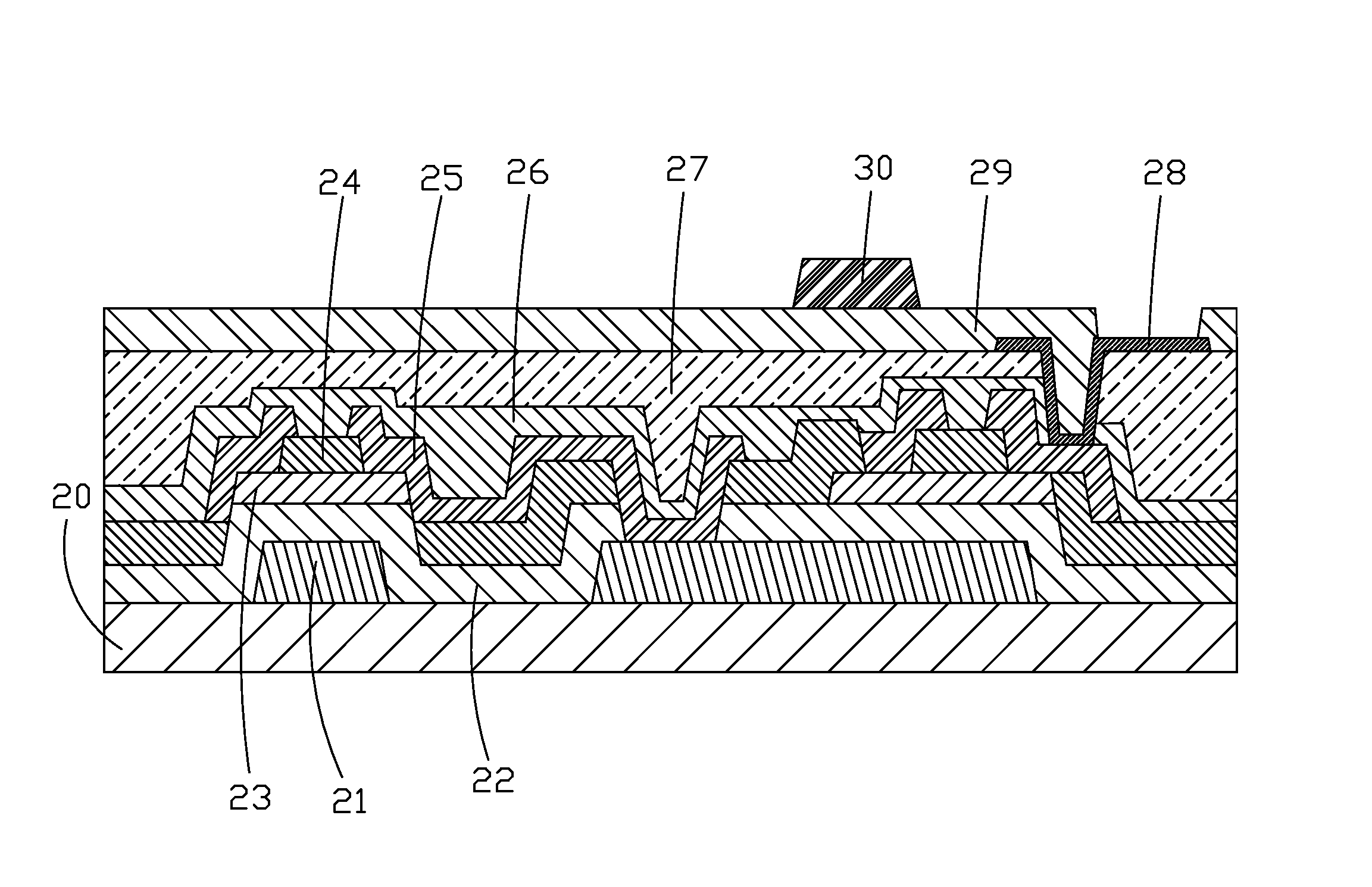
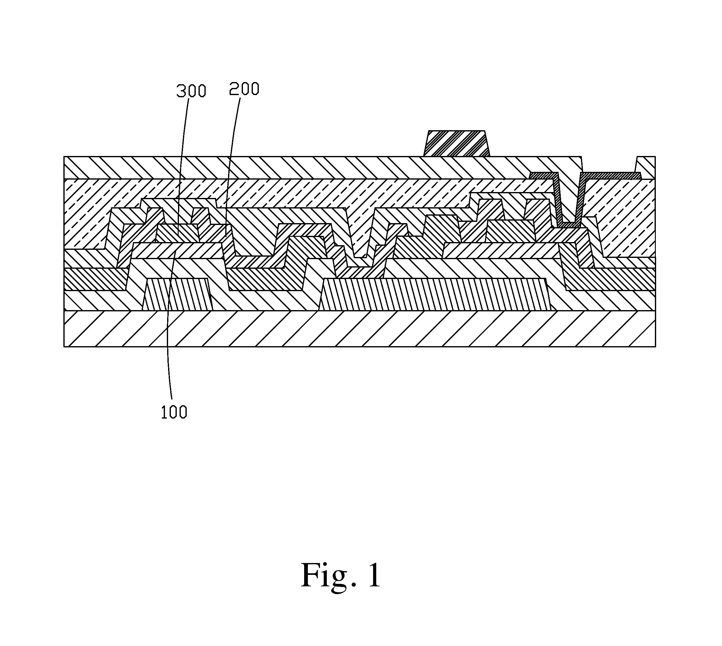
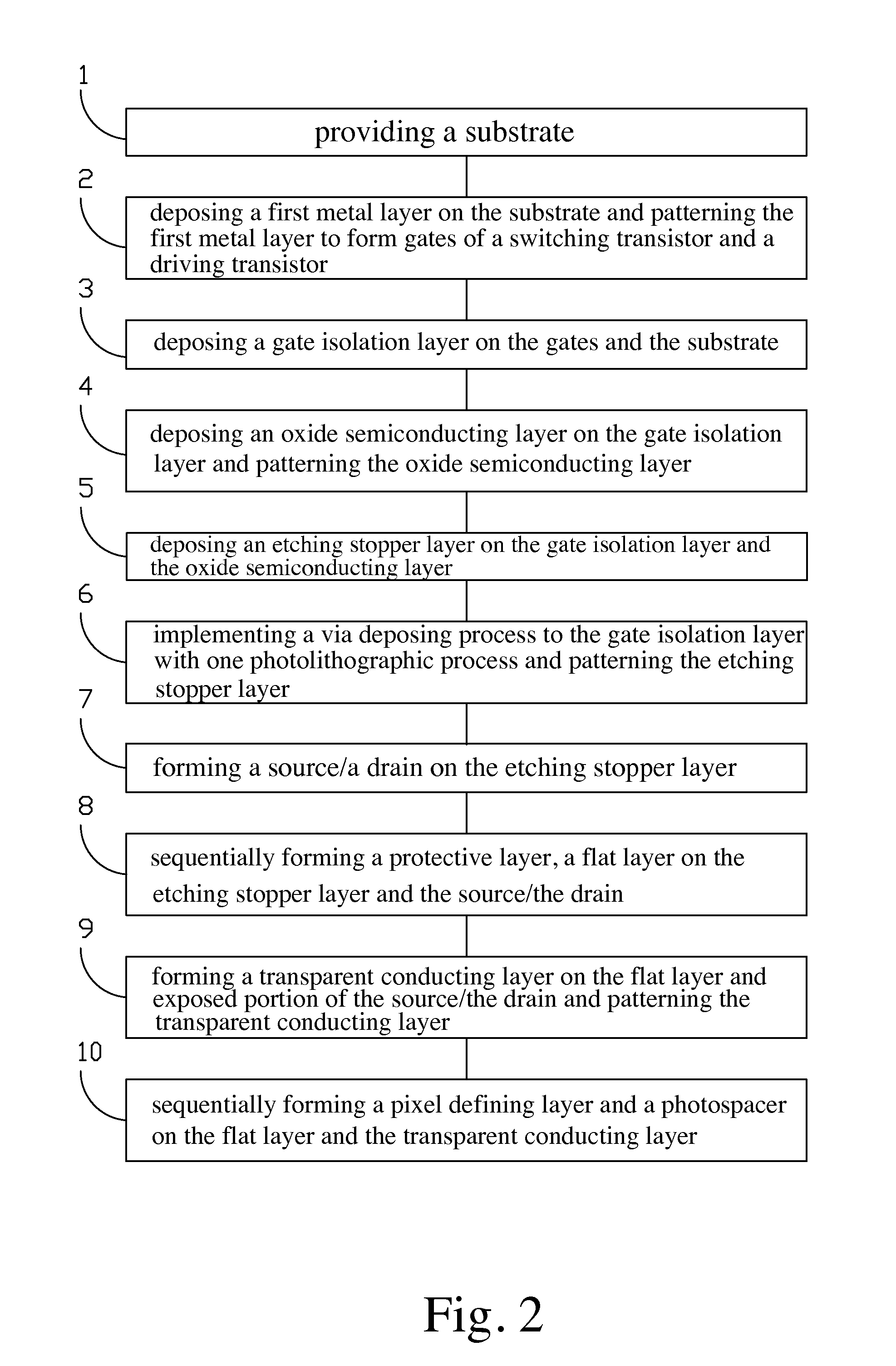
[0055]Please refer to FIG. 2 and from FIG. 3 to FIG. 10. The present invention provides a manufacture method of a thin film transistor substrate, comprising steps of:

[0056]step 1, providing a substrate 20.

[0057]The substrate 20 is a transparent substrate and preferably can be a glass substrate or a plastic substrate. In this embodiment, the substrate 20 is a glass substrate.

[0058]step 2, deposing a first metal layer on the substrate 20 and patterning the first metal layer to form gates 21 of a switching transistor (switching TFT) and a driving transistor (driving TFT).

[0059]Specifically, the first metal layer is formed on the substrate 20 by deposition, and then the exposure, development and etching processes are implemented with a mask or a halftone mask to form a gate 21 with a prede...


PUM


Abstract

The present invention provides a manufacture method of a thin film transistor substrate. In the same photolithographic process, the via deposing process is implemented to the gate isolation layer and the etching stopper layer is patterned. That is, the photolithographic process is not implemented but the oxide semiconducting pattern is formed directly after the gate isolation layer is formed. After the etching stopper layer is formed, the gate isolation layer and the etching stopper layer are patterned in the same photolithographic process. Comparing with the manufacture method of prior art, one photolithographic process can be eliminated. Meanwhile, the aperture ratio is raised by forming an open at the transparent conducting layer.

Description

FIELD OF THE INVENTION[0001]The present invention relates to a skill field of a flat panel display, and more particularly to a manufacture method of a thin film transistor substrate.BACKGROUND OF THE INVENTION[0002]A flat panel display possesses advantages of being ultra thin, power saved and radiation free. It has been widely utilized. A present flat panel display mainly comprises a LCD (Liquid Crystal Display) or an OLED (Organic Light Emitting Display).[0003]An OLED possesses many outstanding properties of self-illumination, no requirement of backlight, high contrast, ultra-thin, wide view angle, fast response, applicability of flexible panel, wide range of working temperature, simpler structure and process. The OLED is considered as next generation flat panel display technology. OLED can be categorized as PM-OLED (Passive matrix OLED) and AM-OLED (Active matrix OLED).[0004]Generally, TFTs (thin film transistor) are utilized in the pixel driving circuit of an AM-OLED. The TFT sub...

Claims


Application Information

Patent Timeline
Patent Type & Authority Applications(United States)
IPC IPC(8): H01L27/12H01L21/3065H01L21/308H01L29/66
CPCG02F1/1368G09F9/30H01L21/3065H01L29/66969H01L27/127H01L27/1288H01L21/3085H01L21/31144H01L29/7869H01L27/1225
Inventor LI, WENHUITSENG, CHIHYUAN
Owner SHENZHEN CHINA STAR OPTOELECTRONICS TECH CO LTD
Learn More