
Self-Fluffing Vehicle Fire Extinguisher

a fire extinguisher and self-fluffing technology, which is applied in fire rescue and other directions, can solve the problems of not meeting the requirements of ul labels, not meeting the standards required, and pressure in the chamber may also leak, etc., and achieves the effect of high strength, easy adaptation, and easy replacement or swapping

Inactive Publication Date: 2016-08-25
ROUSU RANDY +1
View PDF7 Cites 9 Cited by
  • Summary
  • Abstract
  • Description
  • Claims
  • Application Information

AI Technical Summary

Benefits of technology

The self-fluffing vehicle fire extinguisher has two main technical effects. The first effect is that it uses an external pressurized canister, which reduces the need for a high strength chamber and makes the fire extinguisher more portable and easy to replace. The second effect is that it has an externally accessible fluffing mechanism that keeps the powder inside the chamber fluffed and ready to spray on a fire. This mechanism promotes anti-bridging of the powder and helps to keep it in a liquefied state, making it easier to use. The fluffing is achieved with paddles, flapper, chains rods or other mixing mechanisms located inside the chamber, which can be either manually operated or operated with a key.

Problems solved by technology

The pressure within the chamber may also leak over time and be insufficient to propel the powder out of the dispensing nozzle.
A further limitation, based upon this design is due to the pressurized condition of the chamber, powder is placed into the chamber in a small opening in the top of the extinguisher.
They cannot in fact meet the standards required of them.
They cannot meet the requirements of the UL label.
Nor can they meet the manufacturer's requirements.
It is impossible for any service company to meet these requirements.
There are no service vehicles capable of carrying a recovery system for each brand of extinguisher as required by UL.
All extinguishers in service today have contaminated powder and the UL has been voided.
The current system is plagued with serious problems.
The service firms have very little supervision and are in a position to abuse the public.
Most enforcement officers are charged with other more serious duties, i.e. arson etc. and has little time to dedicate to a system that is in fact impossible to maintain.
The vast majorities of service firms operate out of the back of their trucks and are continually on the move, making them difficult to locate and to implement any type of enforcement.
The servicing of current fire extinguishers often creates more wear and tear on the fire extinguisher than when it is used to extinguish a fire.
While these patents disclose a separate pressurized canister, the canister is not located in a position that is easy to service, replace, or inspect.
This minimizes the ability determine the charge level of the CO2 cartridge.
It is known that one of the problems with powder type fire extinguishers is the possibility that the extinguishing powder within the chamber can cake and harden if it is not fluffed to keep the powder in liquid configuration.
Due to the pressurized condition that exists with pressurized fire extinguishers, the opening where powder is placed into the extinguisher is limited due to the structural requirement to maintain pressure within the chamber at all times. The proposed application eliminates this need by providing an external pressurized gas cartridge, thus allowing the chamber to exist in a normally un-pressurized condition.
While these patents disclose a signaling means to announce that the fire extinguisher has been removed, none of them disclose a wireless indicator, or due they provide for a mixing mechanism for fluffing the internal contents of the fire extinguisher.

Method used


Image

  • Self-Fluffing Vehicle Fire Extinguisher
  • Self-Fluffing Vehicle Fire Extinguisher
  • Self-Fluffing Vehicle Fire Extinguisher

Examples


Embodiment Construction

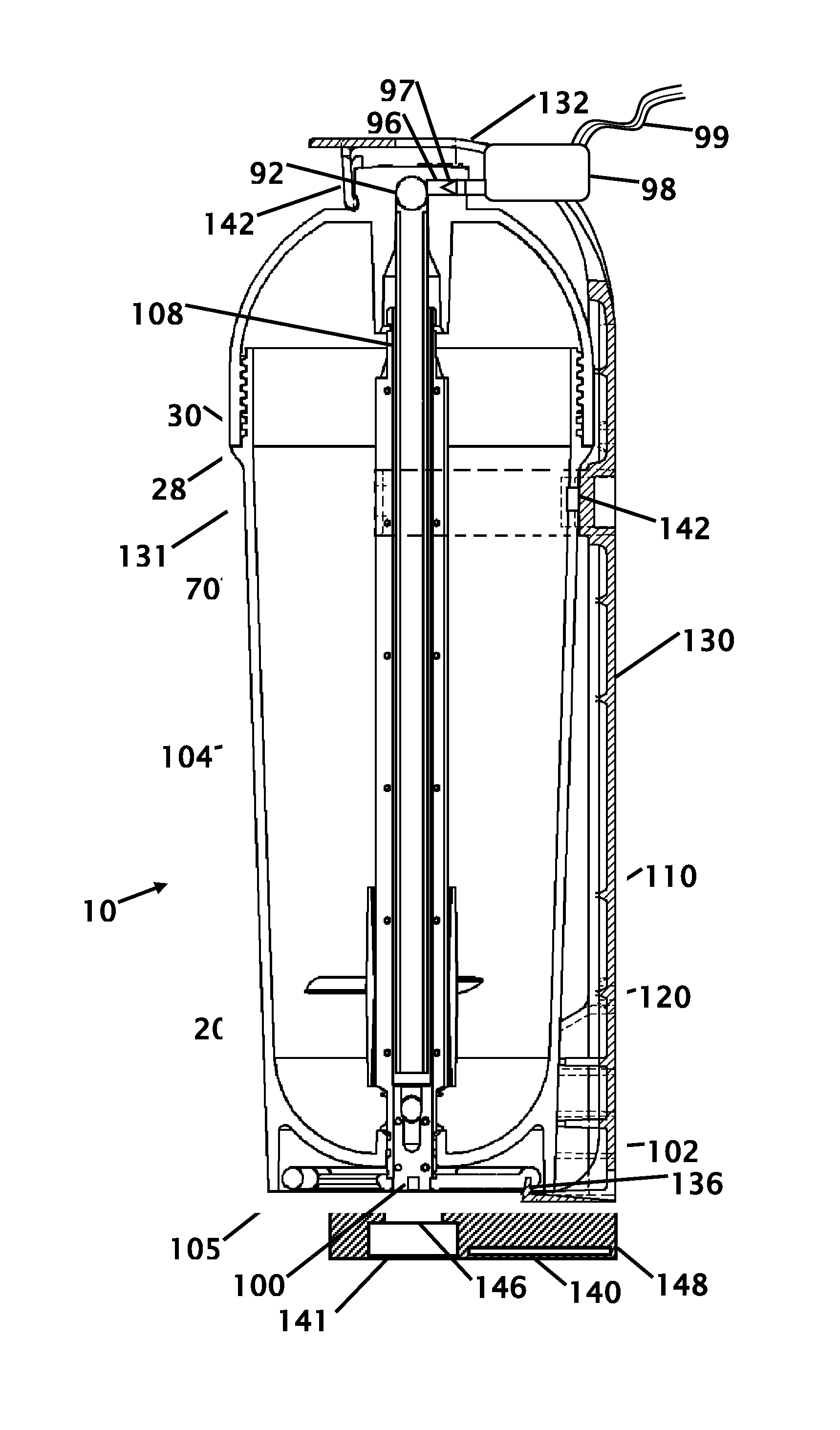
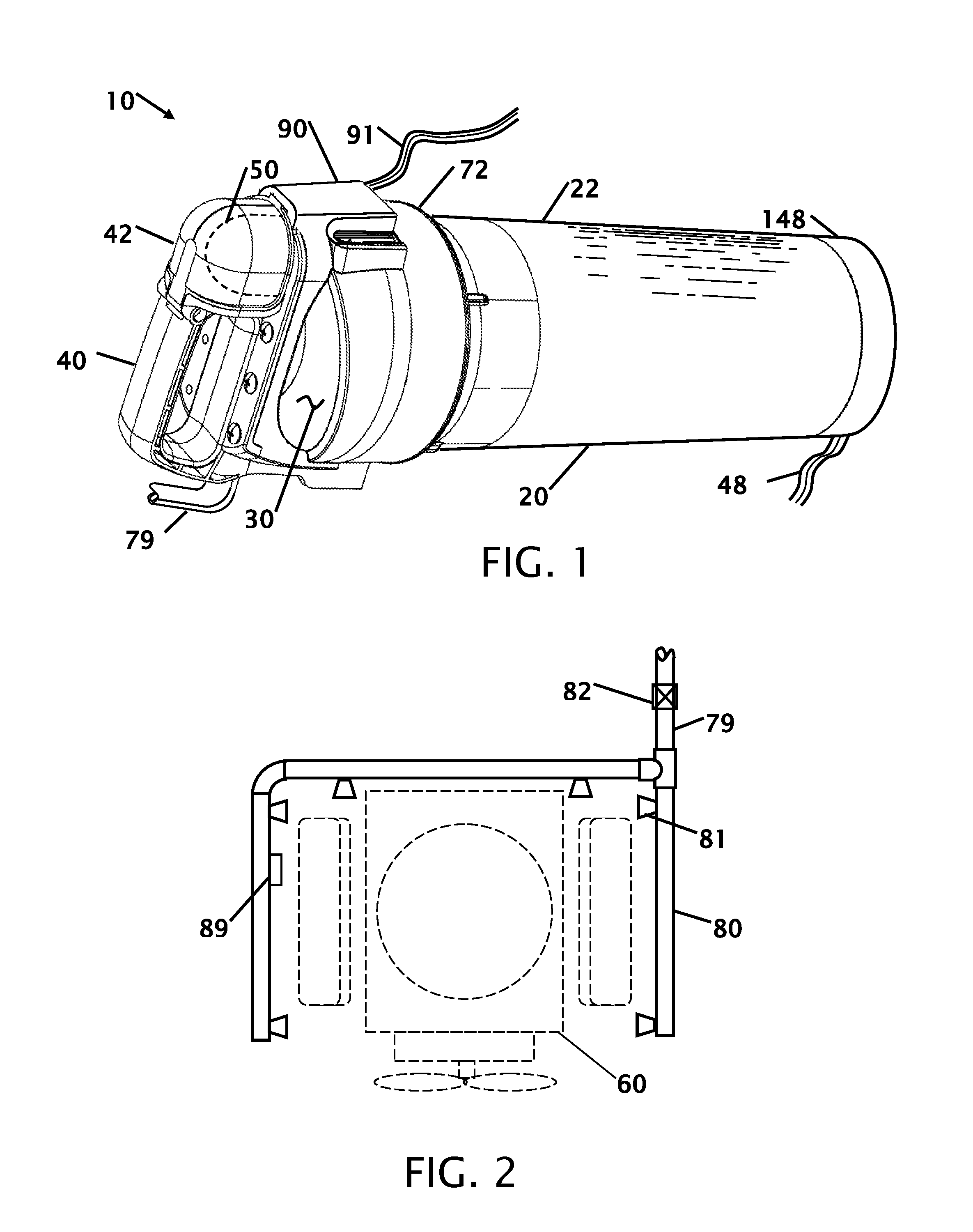
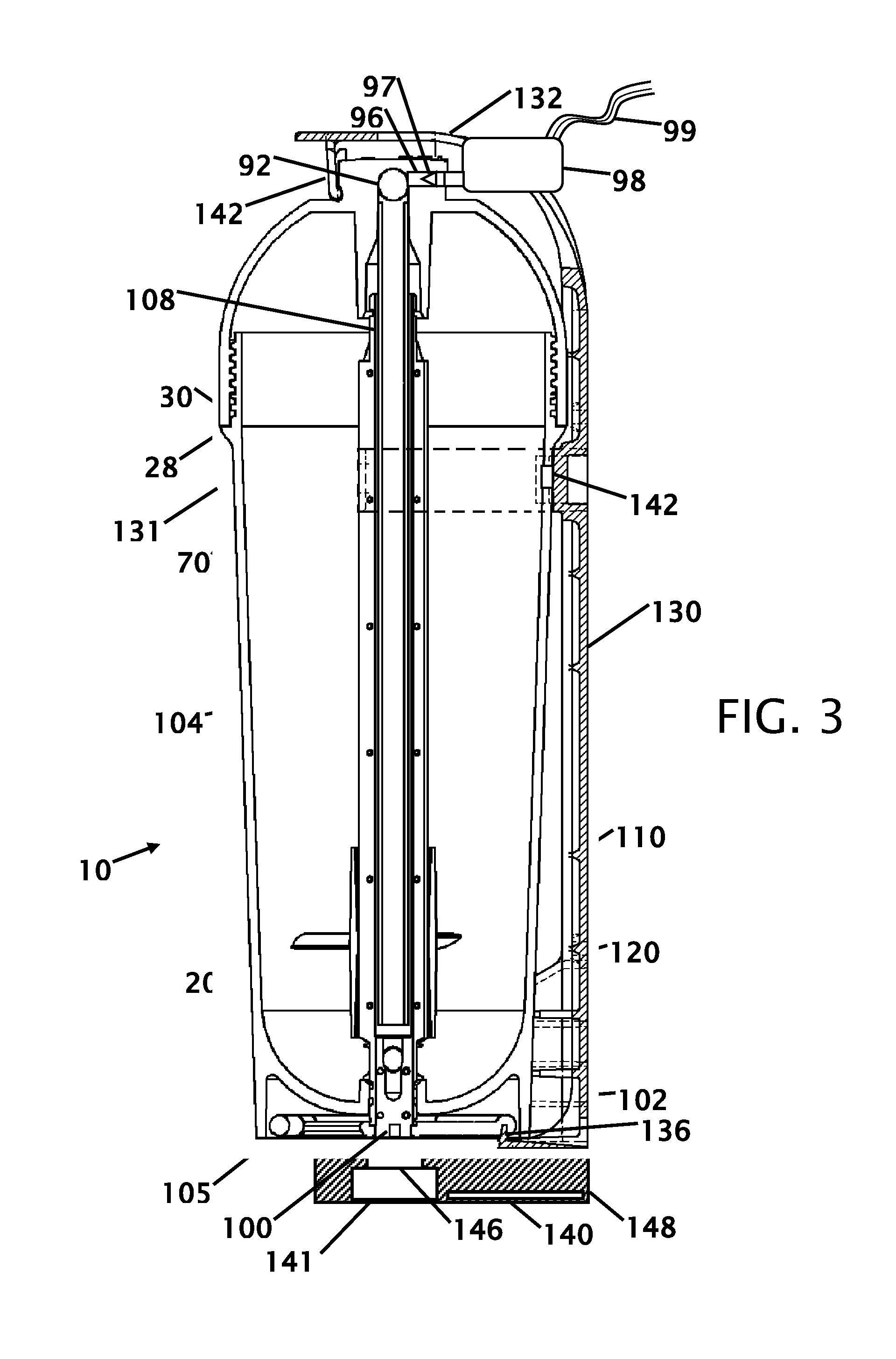
[0031]FIG. 1 an isometric view of the self-reliant fire extinguisher 10. The chamber 20 is substantially a cylindrical shape with a bottom 22 and a top 30 housing. In the preferred embodiment the chamber is molded from a lightweight resilient material, but it is further contemplated that the chamber be made of aluminum, steel, brass or copper. The preferred embodiment of plastics allows the extinguisher to be placed in locations that could cause corrosion of metals. The top 30 is screwed onto the chamber, but it could also be attached with a bayonet or latching mechanism. The top 30 fits on top of an enlarged opening 72 on the chamber to allow easier filling of the chamber 20 with fire retardant materials. A wall hanging mechanism can be incorporated into the top of the extinguisher, wrap around the body of the cylinder or fork the top of the extinguisher. An optional handle 40 allows the operator to hold the extinguisher in an upright or horizontal orientation. The fire extinguishe...


PUM


Abstract

Improvements to a self-fluffing vehicle fire extinguisher where the improvements relate to a system where the extinguisher can be monitored and maintained. Further Improvements include an anti-bridging mechanism that is articulated from the exterior of the chamber to fluff, mix or stir the powder within the chamber to keep it in a liquefied state. An automatic fluffing motor and manual fluffing wheel. Pressurizing the fire extinguisher can be with an external gas chamber or can be with a compressor that maintains the pressure within the extinguisher. A delivery system can direct the fire extinguishing media to an area of the vehicle that has an elevated temperature or can distribute the media thorough the occupied or unoccupied portion of the vehicle.

Description

CROSS REFERENCE TO RELATED APPLICATION[0001]This application is a continuation-in-part of applicant's co-pending application Ser. No. 14 / 745,135 filed on Sep. 8, 2014 which is a continuation-in-part of application Ser. No. 12 / 851,169 filed on Aug. 5, 2010 that issued as U.S. Pat. No. 8,757,282 on Jun. 24, 2014 which is a continuation-in-part of application Ser. No. 11 / 578,494 that was filed on Oct. 12, 2006 which issued as U.S. Pat. No. 7,793,737 on Sep. 14, 2010, which claims priority to international application PCT / US06 / 41 1 57 that was filed on Oct. 12, 2006 which claims priority to application 11 / 515,471 that was filed on Sep. 1, 2006 and issued as U.S. Pat. No. 7,318,484 on Jan. 1, 2015 and application Ser. No. 11 / 226,815 that was filed on Nov. 4, 2005 and issued as U.S. Pat. No. 7,128,163 on Nov. 31, 2006.STATEMENT REGARDING FEDERALLY SPONSORED RESEARCH OR DEVELOPMENT[0002]Not ApplicableTHE NAMES OF THE PARTIES TO A JOINT RESEARCH AGREEMENT[0003]Not ApplicableINCORPORATION-BY...

Claims


Application Information

Patent Timeline
IPC IPC(8): A62C3/07A62C13/00A62C13/76A62C13/66
CPCA62C3/07A62C13/66A62C37/50A62C13/76A62C13/74A62C13/006
Inventor ROUSSEAU, RANDYROUSSEAU, HECTOR
Owner ROUSU RANDY
Learn More