Electronic Control Device

a control device and electronic technology, applied in the direction of coupling device connection, electrical apparatus casing/cabinet/drawer, display/control unit casing, etc., can solve the problem of reducing the reliability of connection, and achieve the effect of contributing to the small size of the device and sufficient connection reliability

Active Publication Date: 2016-08-25
HITACHI ASTEMO LTD
View PDF9 Cites 10 Cited by
  • Summary
  • Abstract
  • Description
  • Claims
  • Application Information

AI Technical Summary

Benefits of technology

[0006]However, in both terminals described above connected from the mutually opposite directions, a load is applied during the connection. Hence, in a case where the tuning fork terminal (the terminal of a thin thickness structure) is merely applied to either one of both terminals, there is a possibility that a connection reliability is reduced due to an unstable connection. Although it is considered that the connection reliability is increased by making the tuning fork terminal thicker, in order to endure the above-described load, or by reinforcing a support structure of the tuning fork terminal (reinforcing using the bus bar), this brings a large sizing of the device.
[0007]The present invention is provided to solve the above-described problem of a conventional art. The problem to be solved by the present invention is that the terminal mounted on the circuit board and the other various kinds of terminals can be connected with a sufficient connection reliability and it can contribute on the small sizing of the device.
[0009]According to the present invention, the other various kinds of terminals are connected to the terminal mounted on the circuit board with a sufficient connection reliability and it can contribute on the small sizing of the device.

Problems solved by technology

Hence, in a case where the tuning fork terminal (the terminal of a thin thickness structure) is merely applied to either one of both terminals, there is a possibility that a connection reliability is reduced due to an unstable connection.

Method used


Image

  • Electronic Control Device
  • Electronic Control Device
  • Electronic Control Device

Examples


Embodiment Construction

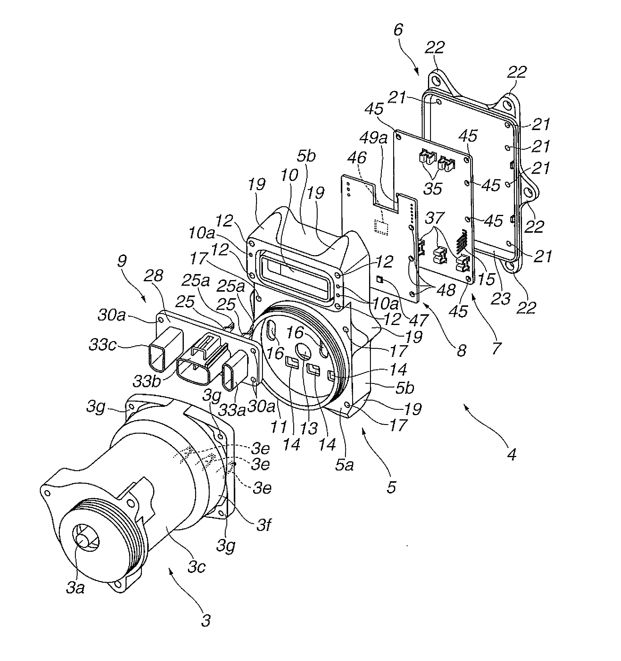
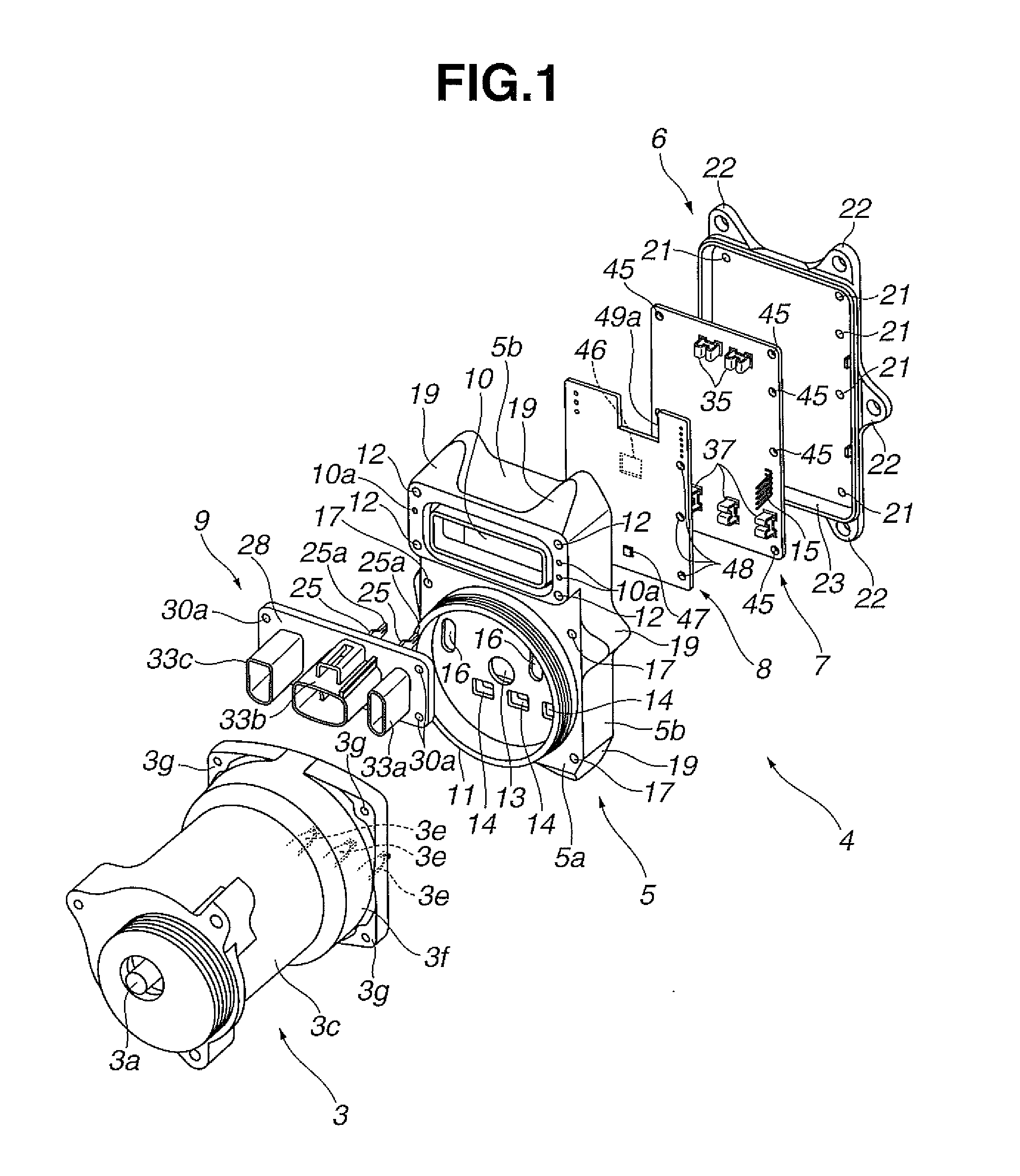
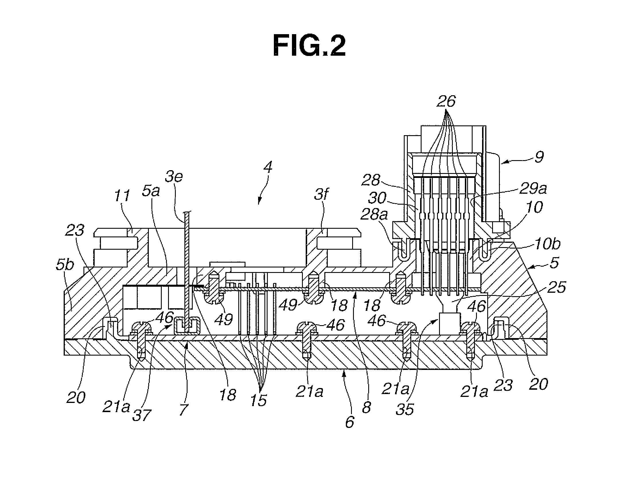
[0020]An electronic control device in a preferred embodiment according to the present invention includes bondable two cabinet members positioned in mutually opposing directions, a circuit board being installed and housed in one of the two cabinet members.

[0021]A first terminal (corresponds to first power supply terminals 25, 3e as will be described later) disposed on the other of the two cabinet members and a second terminal mounted on the circuit board (corresponds to second power supply terminals 35, 37 as will be described later) can be connected together having a sufficient connection reliability (can be connected without use of a tuning fork terminal or so forth). In addition, the electronic control device in the preferred embodiment according to the present invention can contribute on a small sizing of the device.

[0022]Hereinafter, the electronic control device in the preferred embodiment according to the present invention will be explained on a basis of an application example...


PUM


Abstract

An electronic control unit includes a casing and a cover which are mutually bonded. A drive circuit board which drives a motor unit is fixed to the cover and, on the other hand, a control circuit board which controls the drive circuit board is fixed to the casing. An electrical connector which supplies an electric power to each board and a motor unit is attached on an opening section of the casing. First power supply terminals of this electrical connector and the motor unit and second power supply terminals of the drive circuit board are directly electrically connected by a bonding of both of casing and the cover.

Description

TECHNICAL FIELD[0001]The present invention relates to an electronic control device and, for example, relates to the electronic control device which applies to drivingly control an electrically driven motor for such as an electrically driven power steering device (EPS) for a vehicle.BACKGROUND ART[0002]As an electronic control device mounted on the vehicle such as, for example, an electrically driven power steering device, such a structure is known, for example, in a patent document 1 in which a circuit board on which various kinds of electronic parts are mounted is housed in a space of an inside of a cabinet constituted by a plurality of cabinet members (for example, a casing, a cover, and so forth as will be described later) and both of a terminal mounted on the circuit board and other various kinds of terminals (for example, power supply terminals of a bus bar or so forth) are mutually electrically connected by means of a wire bonding or welding (a welding to which a direct curren...

Claims


Application Information

Patent Timeline
Patent Type & Authority Applications(United States)
IPC IPC(8): B62D5/04H05K5/00
CPCB62D5/0406H05K3/0061H05K3/4015H05K2201/0999H05K2201/1031H05K2201/10409H05K5/0004H05K5/0069Y02P70/611H01R12/523H01R12/7088H05K5/0017H05K5/0047H01R13/115Y02P70/50
Inventor HAGIWARA, KATSUMASA
Owner HITACHI ASTEMO LTD
Why Eureka
Try Eureka