Microfluidic sorting using high gradient magnetic fields

a magnetic field and microfluidic technology, applied in the field of microfluidic sorting of analytes using high gradient magnetic fields, can solve the problems of plaque aggregates disrupting the operation of microfluidic devices, cell binding non-specifically to the walls, and limiting the sample volume that can be processed

Active Publication Date: 2016-08-25
THE GENERAL HOSPITAL CORP
View PDF24 Cites 45 Cited by
  • Summary
  • Abstract
  • Description
  • Claims
  • Application Information

AI Technical Summary

Benefits of technology

[0003]The present disclosure is related to sorting magnetic, e.g., magnetically labeled, particles in microfluidic channels using high gradient magnetic fields arranged to help avoid aggregation of the particles near walls of the microfluidic channels. In general, one aspect of the present disclosure can be embodied in microfluidic devices that employ high magnetic field gradients for sorting target particles, e.g., agents or analytes (e.g., nucleic acids, polypeptides, bacteria, and cells) flowing within a microfluidic channel of the device. The devices can include a first array of one, two, or more magnets arranged above the microfluidic channel, and a second array of one, two, or more magnets arranged beneath the channel. The first and second arrays of magnets produce magnetic fields that combine to generate a magnetic flux gradient profile that extends through the microfluidic channel. An absolute value of the magnetic flux gradient profile has a first peak and a second peak that bound a local minimum. The absolute of the gradient between each peak and the local minimum gives rise to a strong magnetic force that can “pull” magnetically labeled particles traveling within the microfluidic channel from the particle's initial trajectory. Depending on the positioning of the gradient profile, aggregation of the magnetically labeled particles near the microfluidic channel walls can be avoided.
[0042]Implementations of the subject matter described herein provide several advantages. For example, by configuring the local minimum in the magnetic flux gradient profile to be located away from the microfluidic channel walls (e.g., near the center of the microfluidic channel), it is possible to reduce or eliminate the formation of plaques on the channel walls, which could otherwise clog the microfluidic channels. In some implementations, the use of inertial focusing in combination with magnetophoresis enhances the efficiency with which magnetic or magnetizable particles can be isolated from unlabeled or non-magnetically labeled particles. In addition, using inertial focusing allows the magnetic or magnetizable particles to be laterally aligned in a microfluidic channel with a desired position of the magnetic flux gradient, such as the position where the magnetic flux gradient is highest or lowest. Combining multiple inertial focused streams into a single channel where magnetophoresis occurs can, in certain instances, improve the throughput of analyte separation and isolation. Furthermore, by using multiple magnetophoresis stages in series, it is possible to improve the efficiency with which targeted analytes are isolated from a fluid sample.

Problems solved by technology

This can result in the cells binding non-specifically to the walls, such that the cells aggregate, e.g., in the form of plaques on the walls.
When large sample volumes are processed such plaque aggregation limits the sample volume that can be processed.
In addition to clogging the device, the plaque aggregates can disrupt microfluidic device operation when large chunks of plaque break off (“burp”) from the primary plaque aggregate on the channel wall.
These chunks of plaque can contain hundreds or thousands cells and their behavior in the microfluidic device may be unpredictable and difficult to control.

Method used


Image

  • Microfluidic sorting using high gradient magnetic fields
  • Microfluidic sorting using high gradient magnetic fields
  • Microfluidic sorting using high gradient magnetic fields

Examples


example 1

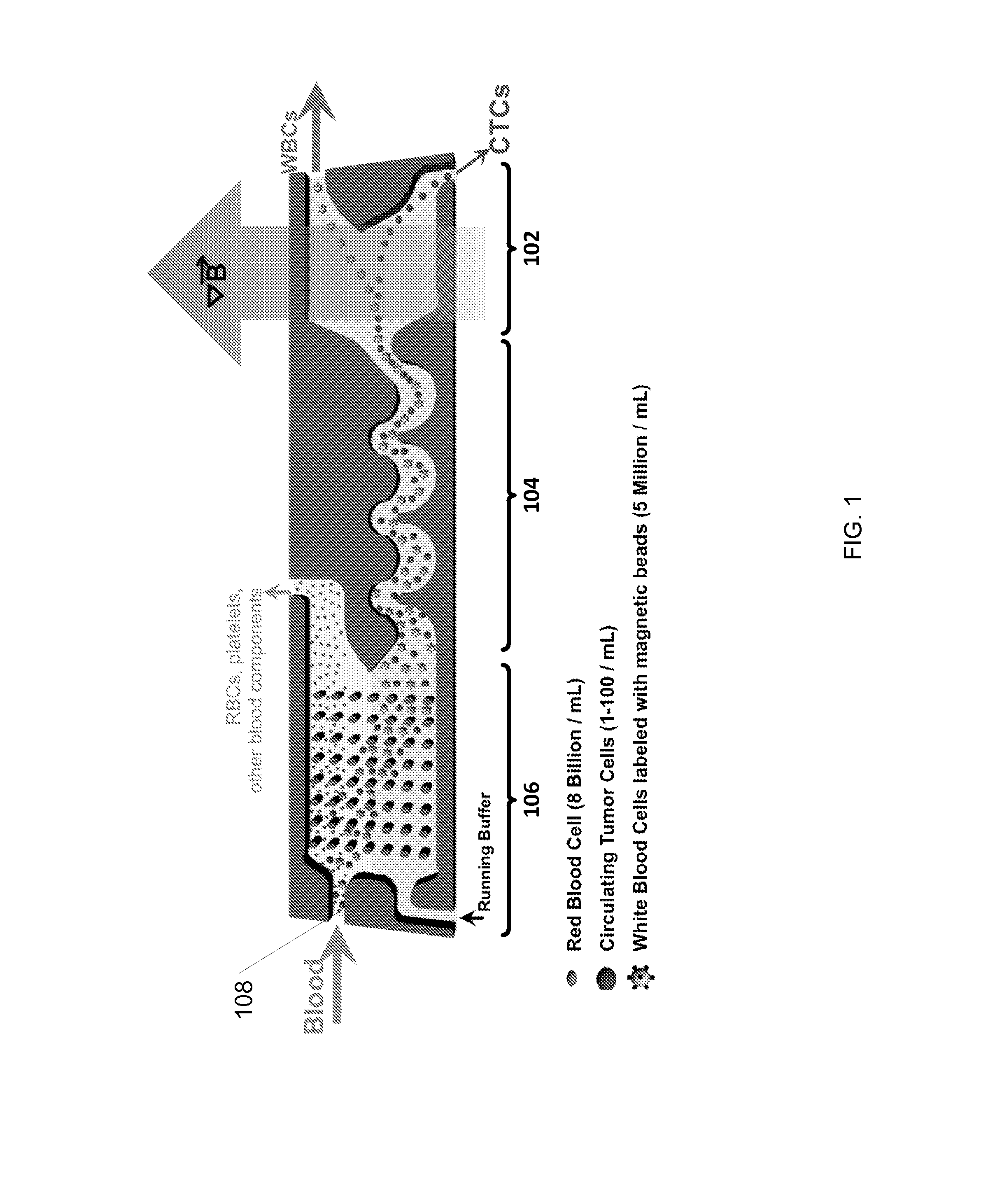
Isolating Cancer Cells in Blood

[0155]The purpose of this example was to simulate a cancer patient's blood by spiking cell line cancer cells to represent circulating tumor cells (CTCs) into a healthy donor's blood sample, efficiently tagging white blood cells with magnetic beads, and removing the tagged white blood cells using magnetophoresis to isolate the cancer cells for detection and / or further measurements. The protocol below describes the isolation of CTCs using a system that employed continuous (i) deterministic lateral displacement (hydrodynamic cell sorting) for size-based separation of both white blood cells and tumor cells from whole blood, (ii) inertial focusing for precise positioning of these cells in a micro-channel, followed by (iii) microfluidic magnetophoresis for immune-magnetic isolation of circulating tumor cells. The example process described herein was conducted using two separate chips (named “CTC-iChip1” and “CTC-iChip2”), that were serial (inline) fluid comm...

example 2

Examining Device Robustness and Effectiveness

[0173]Additional studies also were performed using copies of the CTC-iChip1 and CTC-iChip2 designs described above in Example 1. In particular, the CTC-iChip1 and CTC-iChip2 systems were fabricated (as described in Example 1) for performing similar but separate experiments at three different research sites so as to review the robustness and effectiveness of deterministic lateral displacement, inertial focusing and magnetophoresis techniques (as combined in the CTC-iChip configuration) for isolating circulating tumor cells from whole blood samples and the depletion of white blood cells. The three research sites are referenced below as “JRD,”“JDX,” and “MGH.” Blood samples were prepared and processed for each experiment using the following workflow: (a) blood sample acquisition from donors and sample preparation, (b) isolation of CTCs using the iChip configuration (CTC-iChip1 and CTC-iChip2) as fabricated above, (c) plating of the isolated ...


PUM

PropertyMeasurementUnit
distanceaaaaaaaaaa
distanceaaaaaaaaaa
distanceaaaaaaaaaa

Abstract

Microfluidic devices are described that include a microfluidic channel, a first array of one or more magnets above the microfluidic channel, each magnet in the first array having a magnetic pole orientation opposite to a magnetic pole orientation of an adjacent magnet in the first array, and a second array of one or more magnets beneath the microfluidic channel, each magnet in the second array having a magnetic pole orientation opposite to a magnetic pole orientation of an adjacent magnet in the second array. The first array is aligned with respect to the second array such that magnetic fields emitted by the first array and second array generate a magnetic flux gradient profile extending through the channel. An absolute value of the profile includes a first maximum and a second maximum that bound a local minimum. The local minimum is located within the microfluidic channel or less than 5 mm away from a wall of the microfluidic channel. Methods of using the new devices are also described.

Description

TECHNICAL FIELD[0001]The present disclosure relates to microfluidic sorting of analytes using high gradient magnetic fields.BACKGROUND[0002]Magnetic cell separation is a technique in which magnetic fields are used to isolate cells within a fluid sample. Typically, magnetic particles are selectively attached to one or more desired cells using antibodies that bind to the cell surface. Cells having the attached magnetic particles then can be confined or deflected within a microfluidic device using an applied magnetic field to isolate the magnetically labeled cells from other analytes in the fluid sample. In some instances, the flow velocities, and thus the shear forces exerted on the cells, approach zero near the fluid channel walls of the device. This can result in the cells binding non-specifically to the walls, such that the cells aggregate, e.g., in the form of plaques on the walls. When large sample volumes are processed such plaque aggregation limits the sample volume that can be...

Claims


Application Information

Patent Timeline
Patent Type & Authority Applications(United States)
IPC IPC(8): C12M1/00B03C1/033C12M3/06B03C1/01
CPCG01N35/0098C12M47/04G01N2015/149G01N2035/00237G01N2035/1034G01N15/1463B03C1/01B03C1/0332B03C1/288B03C2201/18B03C2201/26B01L3/502753B01L3/502761B01L2200/0652B01L2300/0816B01L2300/0864B01L2400/043B01L2400/0487B01L2400/086C12M23/16G01N2015/1006B03C2201/22B01L3/00B03C1/0335C12M35/06G01N15/1484G01N1/00
Inventor SPUHLER, PHILIPP S.SMITH, KYLE C.FACHIN, FABIOBARBER, THOMAS ALANKAPUR, RAVITONER, MEHMETPAI, VINCENTKARABACAK, MURAT N.
Owner THE GENERAL HOSPITAL CORP
Why Eureka
Try Eureka