Hydraulic circuit for power transmission device of vehicle

a technology of power transmission device and hydraulic circuit, which is applied in the direction of multiple way valves, engine components, mechanical apparatus, etc., can solve the problems of increasing manufacturing cost, pressure loss, deterioration of mountability and fuel efficiency, etc., and achieve the effect of stabilizing the valve opening characteristi

Active Publication Date: 2016-08-25
TOYOTA JIDOSHA KK
View PDF6 Cites 7 Cited by
  • Summary
  • Abstract
  • Description
  • Claims
  • Application Information

AI Technical Summary

Benefits of technology

[0005]However, such provision of the air bleeding orifice in the discharge oil passage of the oil pump allows hydraulic oil to flow out from the air bleeding orifice even during normal pump operation thereby causing a pressure loss. Thus, the discharge performance of the oil pump must be increased by a corresponding amount, so that the size of the oil pump is increased, thereby deteriorating mountability and fuel efficiency and increasing manufacturing cost.
[0006]The present invention provides a pump which suppresses the pressure loss during normal pump operation in case where the air bleeding orifice is provided on the discharge oil passage of the oil pump and has substantially the same discharge performance as conventionally.

Problems solved by technology

However, such provision of the air bleeding orifice in the discharge oil passage of the oil pump allows hydraulic oil to flow out from the air bleeding orifice even during normal pump operation thereby causing a pressure loss.
Thus, the discharge performance of the oil pump must be increased by a corresponding amount, so that the size of the oil pump is increased, thereby deteriorating mountability and fuel efficiency and increasing manufacturing cost.

Method used


Image

  • Hydraulic circuit for power transmission device of vehicle
  • Hydraulic circuit for power transmission device of vehicle
  • Hydraulic circuit for power transmission device of vehicle

Examples


Embodiment Construction

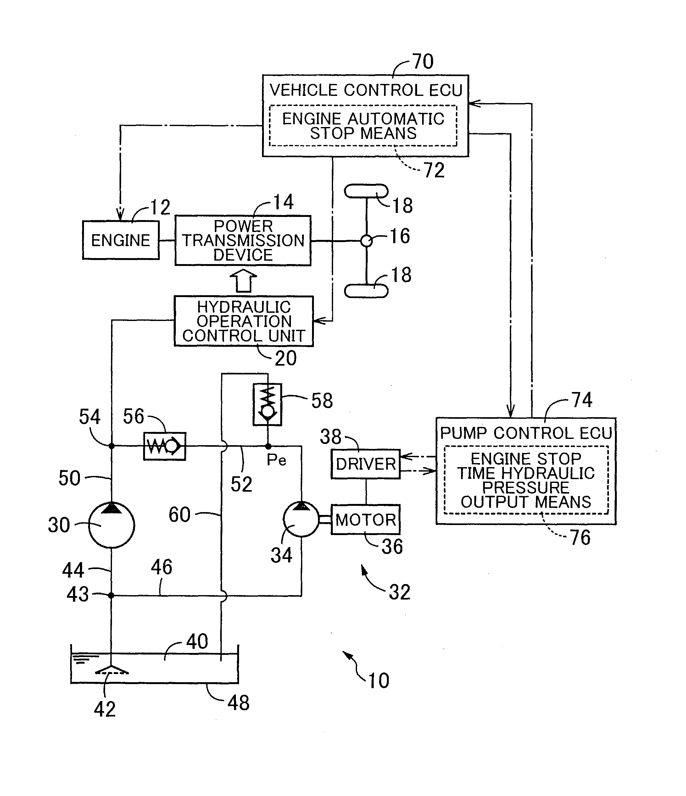
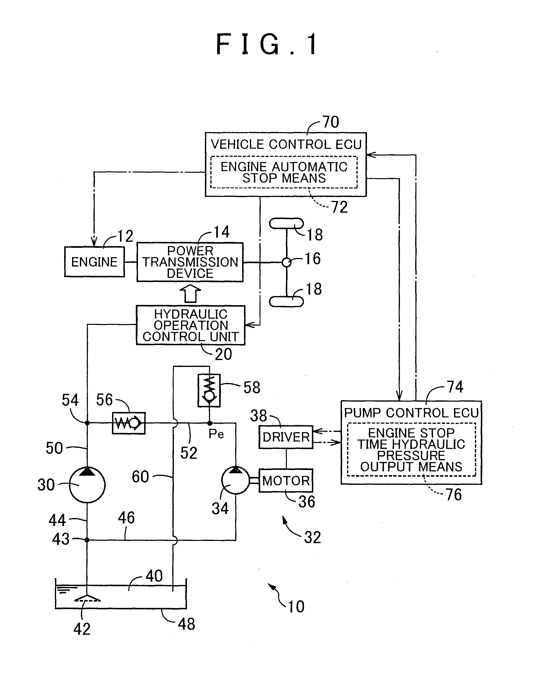
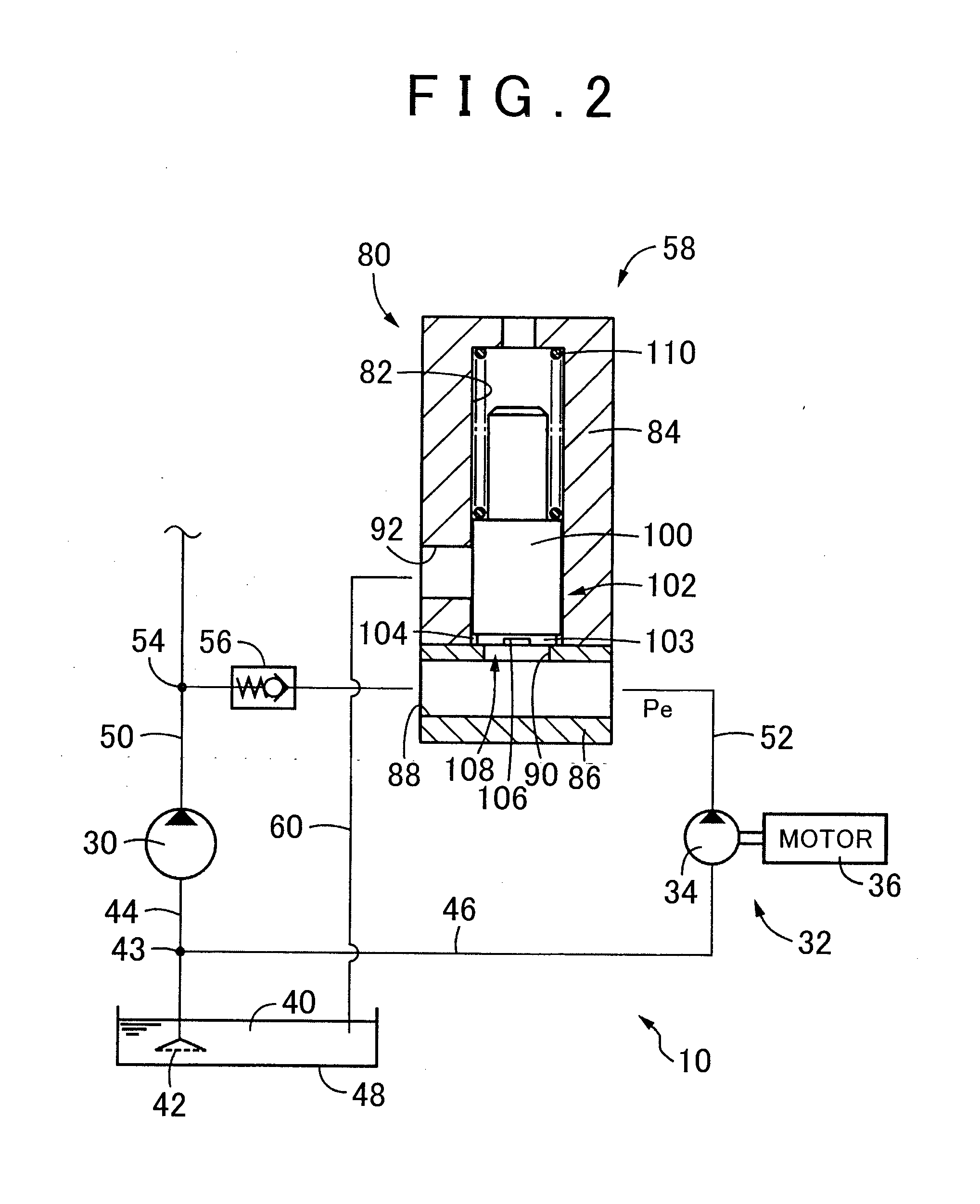
[0036]The present invention can be applied to a hydraulic circuit of a power transmission device for various vehicles such as an engine-driven vehicle having only an internal combustion engine as its traveling power source, a hybrid vehicle having the internal combustion engine and an electric motor, and an electric vehicle having only an electric motor. The power transmission device for the vehicle includes, for example, a belt type continuously variable transmission in which belt compression force or transmission gear ratio is controlled by a hydraulic actuator, stepped automatic variable transmission containing a plurality of friction engaging units (clutch, brake) which are engaged by each of hydraulic actuators to switch a plurality of gear positions each having a different transmission gear ratio, and a forward / backward switching device for switching forward / backward traveling by means of a friction engaging unit (clutch, brake) which is engaged by the hydraulic actuator. Hydr...


PUM


Abstract

A fitting clearance of a relief valve functions as an air bleeding orifice. When a discharge pressure reaches a relief pressure so that the relief valve turns into a relief state, a spool is moved so as to limit flow-out of hydraulic oil through the fitting clearance. As a result, generation of air trapping is suppressed by air bleeding function of the relief valve in a closed state. Air in a discharge oil passage is discharged quickly in the initial period of the startup of an electric oil pump, thereby improving rise-up of discharge pressure. During normal pump operation in which the relief valve is held in a relief state, pressure loss due to flow out of the hydraulic oil from the fitting clearance is suppressed and consequently, an electric oil pump having substantially the same discharge performance as conventionally can be used.

Description

BACKGROUND OF THE INVENTION[0001]1. Field of the Invention[0002]The present invention relates to a hydraulic circuit for a power transmission device of a vehicle and more particularly, to improvement of the hydraulic circuit in which a discharge oil passage of an oil pump thereof is provided with an air bleeding orifice.[0003]2. Description of Related Art[0004]There has been known a hydraulic circuit of a power transmission device for a vehicle which includes (a) an oil pump for use as a hydraulic pressure source of hydraulic oil for actuating a hydraulic actuator of the power transmission device for the vehicle and (b) an air bleeding orifice which is provided so as to communicate with the discharge oil passage of the oil pump and discharge air in the discharge oil passage. Because hydraulic oil in the power transmission device is generally used as lubricant also, air is mixed during stirring at the time of lubrication. In addition, when the hydraulic oil is returned to an oil tank...

Claims


Application Information

Patent Timeline
Patent Type & Authority Applications(United States)
IPC IPC(8): F16H61/02F16K11/07F16H61/00
CPCF16H2061/004F16H61/0031F16K11/07F16H61/0276F16H2061/0279F16H61/0267
Inventor WATANABE, YASUYUKIKUWABARA, SHINYAMIZUNO, YOSHIHIRO
Owner TOYOTA JIDOSHA KK
Why Eureka
Try Eureka