Intermittent Thermosyphon

a thermosyphon and intermittent technology, applied in indirect heat exchangers, lighting and heating apparatuses, laminated elements, etc., can solve the problems of limited maximum boiling heat transfer coefficient, high pressure loss, and limited maximum heat transport distance and/or power

Active Publication Date: 2016-08-25
J R THERMAL LLC
View PDF32 Cites 13 Cited by
  • Summary
  • Abstract
  • Description
  • Claims
  • Application Information

AI Technical Summary

Benefits of technology

[0005]This invention is directed toward thermosyphon technology. Certain embodiments are intended for use in electronics cooling applications, wherein a looped flow pattern through channels is formed by fins in the evaporator as well as in the condenser, while allowing for low pressure loss through these channels, thereby enabling this configuration to be applied in low profile systems where the gravitationally-induced liquid pressure head is limited.
[0006]The liquid supplied to the evaporator is intermittent, and passively regulated by the back flow of vapor bubbles. The passively regulated liquid supply enables enhanced solid / liquid / vapor contact, which yields high heat transfer rates on the channels within the evaporator. This characteristic is a solution to the limitations associated with pool boiling in an evaporator flooded with liquid.
[0007]Additionally, the problem of flow instabilities of expanding vapor bubbles in confined channels is addressed through a series of minor vapor and liquid distribution channels cutting across the major channels on the surface. These channels help enable the liquid and vapor to be stratified in a confined space, which provides a free path for vapor to escape the evaporator with minimum impedance of the liquid phase. Additionally, the liquid distribution allows for the bottom of the fins to maintain a wetted region, and maintain stable performance.
[0008]In various embodiments of the condenser, the vapor flow helps drag liquid along with it from the vapor intake orifices to the liquid exit orifice. The liquid exit orifice is located at the bottom of the fins, which helps minimize the required refrigerant charge as well as keeps the fins free from collected liquid, which can block the condensation process.

Problems solved by technology

The pumping effect in this device requires a wick, which produces a high pressure loss and limits the maximum heat transport distance and or power that can be supported before dry-out occurs.
The maximum boiling heat transfer coefficient can be limited in this device because there are a finite amount of nucleation sites, and therefore a limited length of solid / liquid / vapor contact, where the heat transfer rate is the highest.
This phenomena poses a few problems.
One problem is that the pressure drop associated with high liquid velocities in a channel are quite high, especially relative to the small available pressure head in a thermosyphon device.
A second problem that this phenomena can cause is that the middle of the channel is left dry and can increase in temperature, since the vapor has limited heat capacitance.

Method used


Image

  • Intermittent Thermosyphon
  • Intermittent Thermosyphon
  • Intermittent Thermosyphon

Examples


Embodiment Construction

[0029]The present invention is directed to an improved intermittent thermosyphon. The configuration and use of the presently preferred embodiments are discussed in detail below. It should be appreciated, however, that the present invention provides many applicable inventive concepts that can be embodied in a wide variety of contexts other than an intermittent thermosyphon. Accordingly, the specific embodiments discussed are merely illustrative of specific ways to make and use the invention, and do not limit the scope of the invention. In addition, the following terms shall have the associated meaning when used herein:

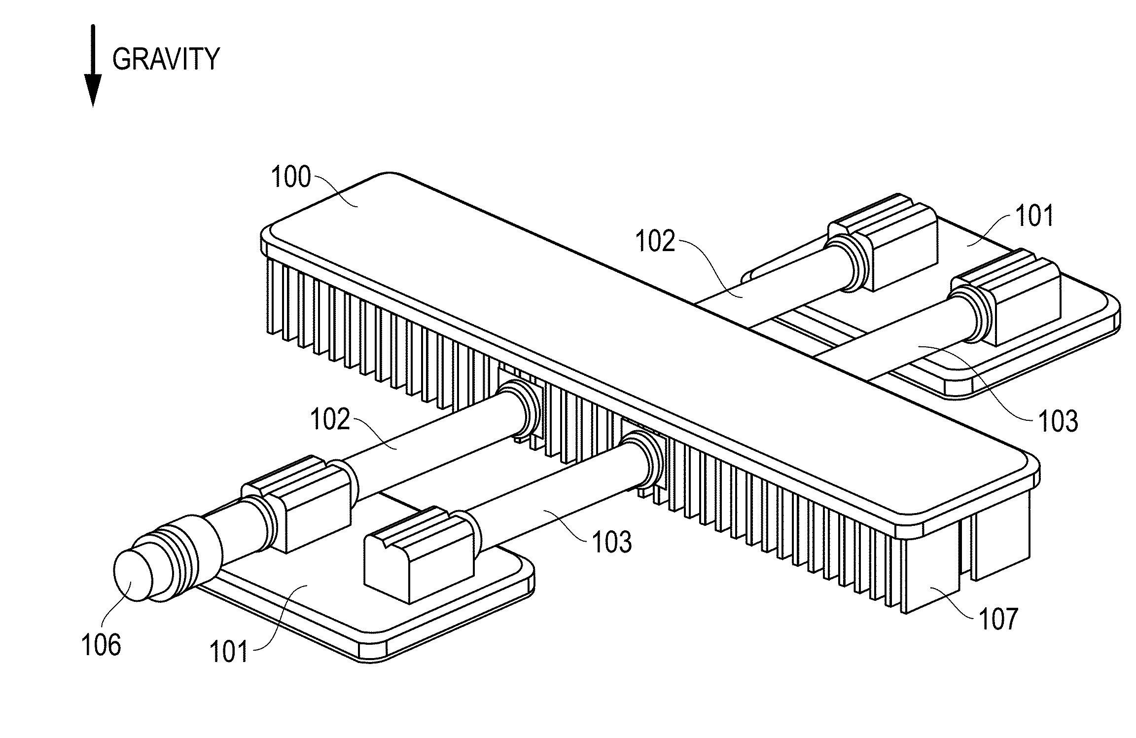
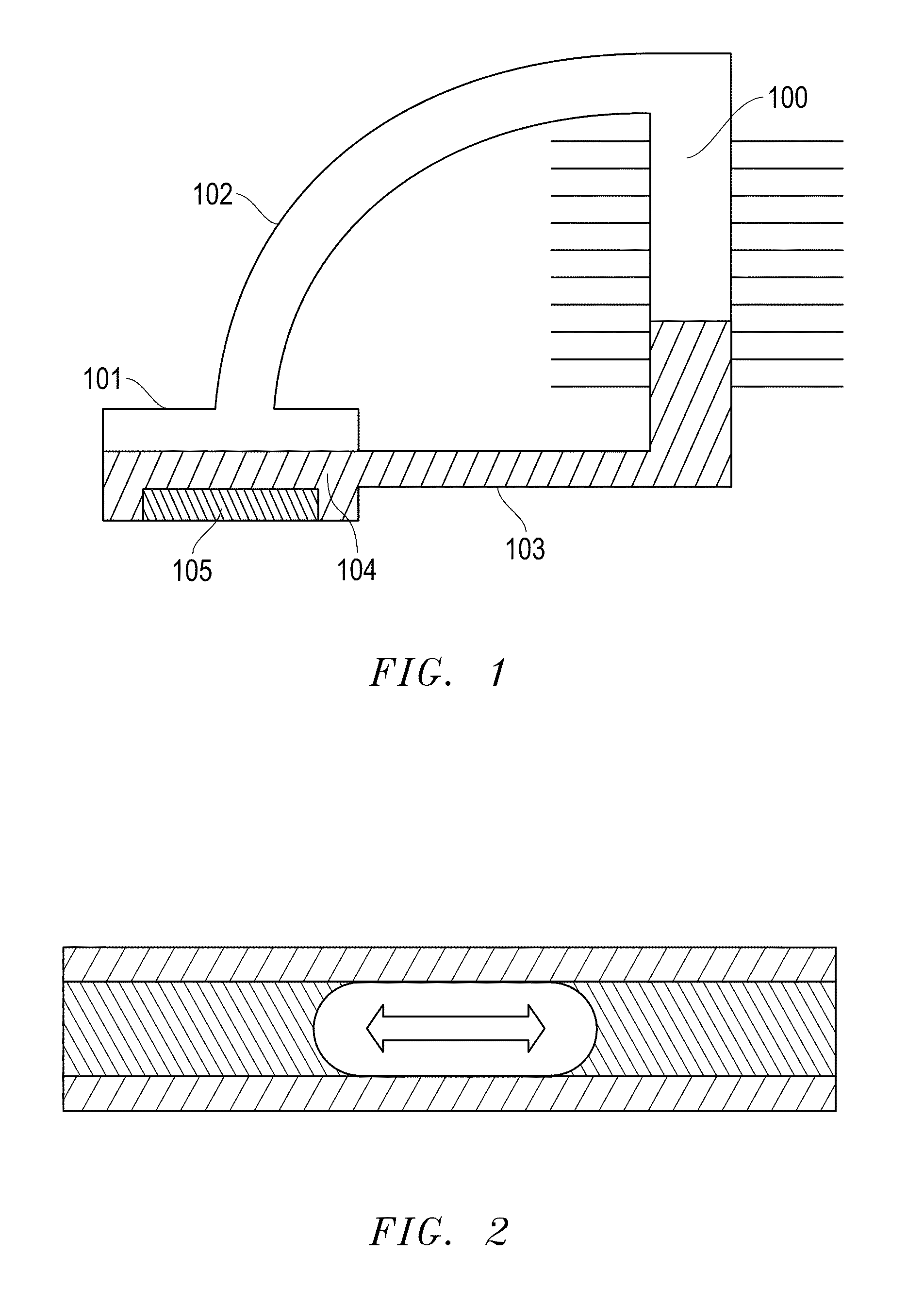
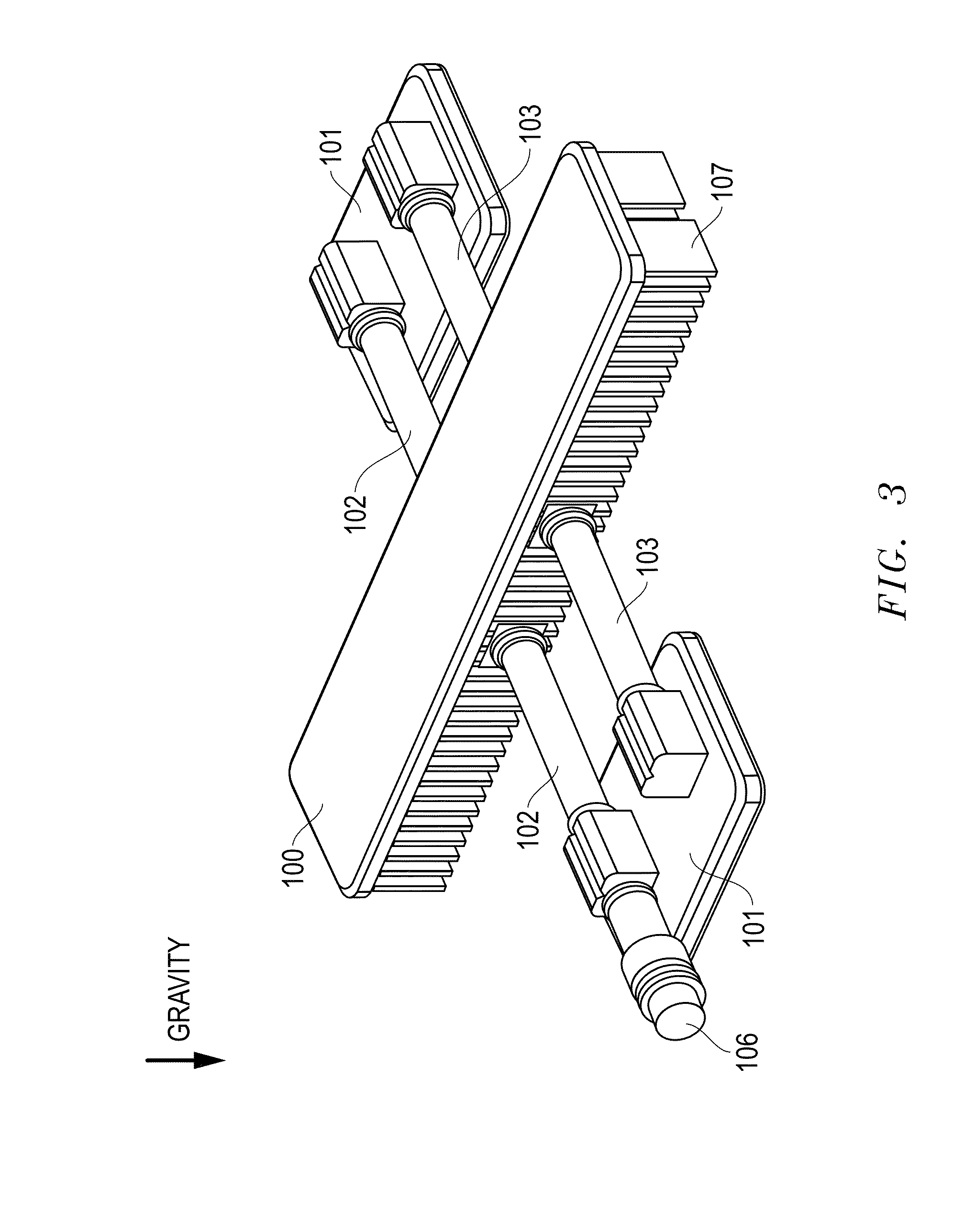
[0030]One embodiment of the present invention is presented in FIG. 3. It includes a condenser 100, two evaporators 101, a vapor tube 102 connecting the evaporator 101 to the condenser 100 primarily transferring vapor, a liquid tube 103 connecting the condenser 100 to the evaporator 102 primarily transferring liquid, and an access valve 106, to pull a vacuum, charge and ...


PUM


Abstract

The device and methods described herein relate to the isothermal heat transport through an intermittent liquid supply to an evaporator device, thereby enabling high evaporative heat transfer coefficients. A liquid and vapor mixture flows through miniature and micro-channels in an evaporator and addresses flow instabilities encountered in these channels as bubbles rapidly expand. Additionally, a high percentage of the fins are exposed to vapor and limit the required charge of refrigerant within the system due to effective condensate removal in the condenser.

Description

PRIORITY STATEMENT UNDER 35 U.S.C. §119 & 37 C.F.R. §1.78[0001]This non-provisional application claims priority based upon prior U.S. Provisional Patent Application Ser. No. 62 / 118,144 filed Feb. 19, 2015 in the name of Jeremy Rice entitled “Intermittent Thermosyphon,” the disclosure of which is incorporated herein in its entirety by reference as if fully set forth herein.BACKGROUND OF THE INVENTION[0002]Passive heat transfer devices, such as heat pipes, are of much interest in applications such as electronics cooling. Heat pipes are a liquid and vapor device in which liquid is pumped through capillarity from the condenser to the evaporator. The pumping effect in this device requires a wick, which produces a high pressure loss and limits the maximum heat transport distance and or power that can be supported before dry-out occurs.[0003]Another technology node that is useful is a thermosyphon as shown in FIG. 1. In operation, liquid 104 is vaporized in an evaporator 101. The vapor the...

Claims


Application Information

Patent Timeline
Patent Type & Authority Applications(United States)
IPC IPC(8): F28D15/02
CPCF28D15/0266F28D15/0233F28D15/0275F28D15/046F28F3/025F28F13/06
Inventor RICE, JEREMY
Owner J R THERMAL LLC
Why Eureka
Try Eureka