

Cordierite-type ceramic honeycomb structure and its production method
Active Publication Date: 2016-09-01
HITACHI METALS LTD
View PDF3 Cites 7 Cited by
- Summary
- Abstract
- Description
- Claims
- Application Information
AI Technical Summary
Benefits of technology
[0011]Accordingly, an object of the present invention is to provide a cordierite-type ceramic honeycomb structure capable of carrying an increased amount of a catalytic material per a unit volume without increasing press
Problems solved by technology
Using such honeycomb structure having thin walls and a high cell density, however, each exhaust-gas-flowing cell of the honeycomb structure has a small opening area, resulting in pressure loss at its inlet.
However, an SCR catalyst comprising as a carrier the ceramic honeycomb structure described in JP 2005-052750 A, the cordierite ceramic product described in JP 2009-542570 A, the porous ceramic body described in JP 2011-516371 A, or the ceramic honeycomb structure used in the ceramic honeycomb filters described in WO 2011/102487 and WO 2011/027837 fails to exhibit satisfactorily high cleaning e
Method used
View moreImage
Smart ImageViewing Examples

Examples
 PUM
| Property | Measurement | Unit |
|---|---|---|
| Length | aaaaa | aaaaa |
| Length | aaaaa | aaaaa |
| Length | aaaaa | aaaaa |
Abstract
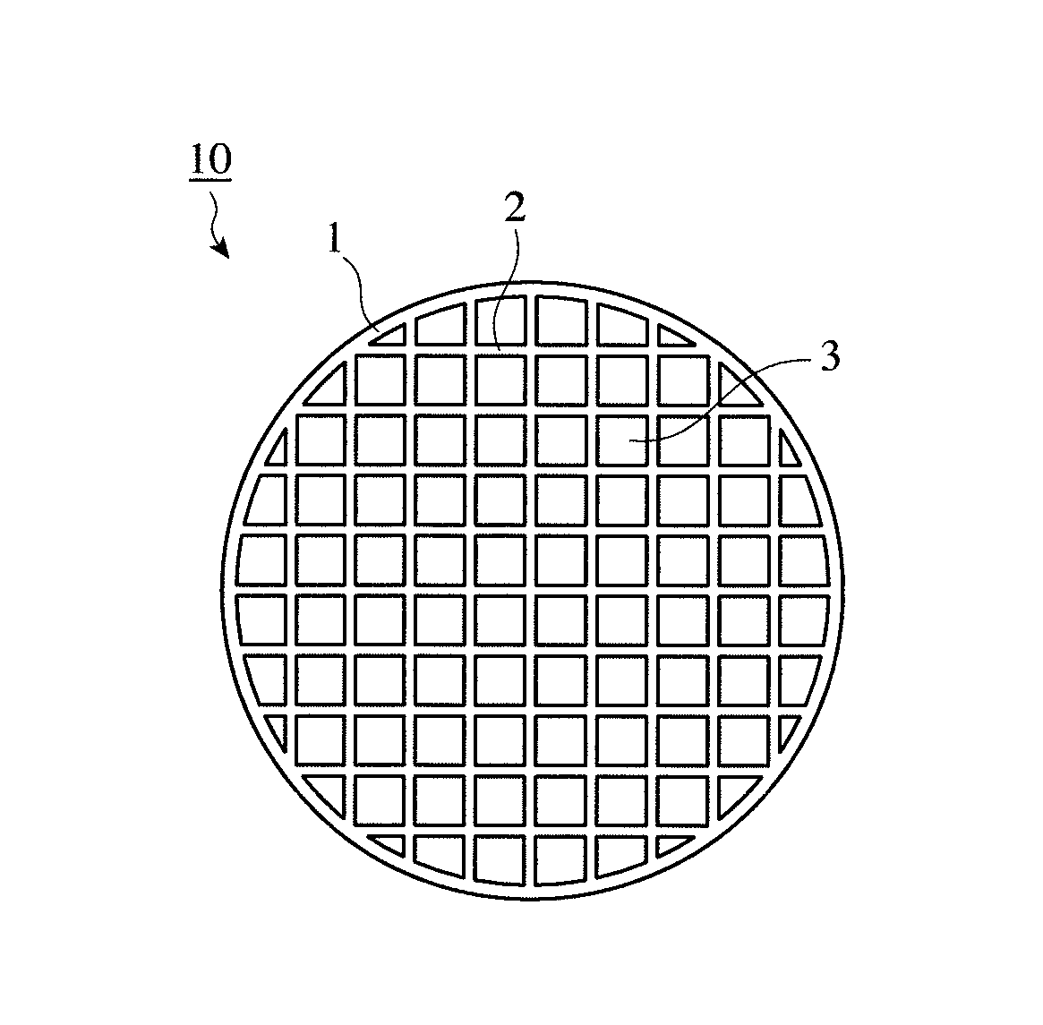
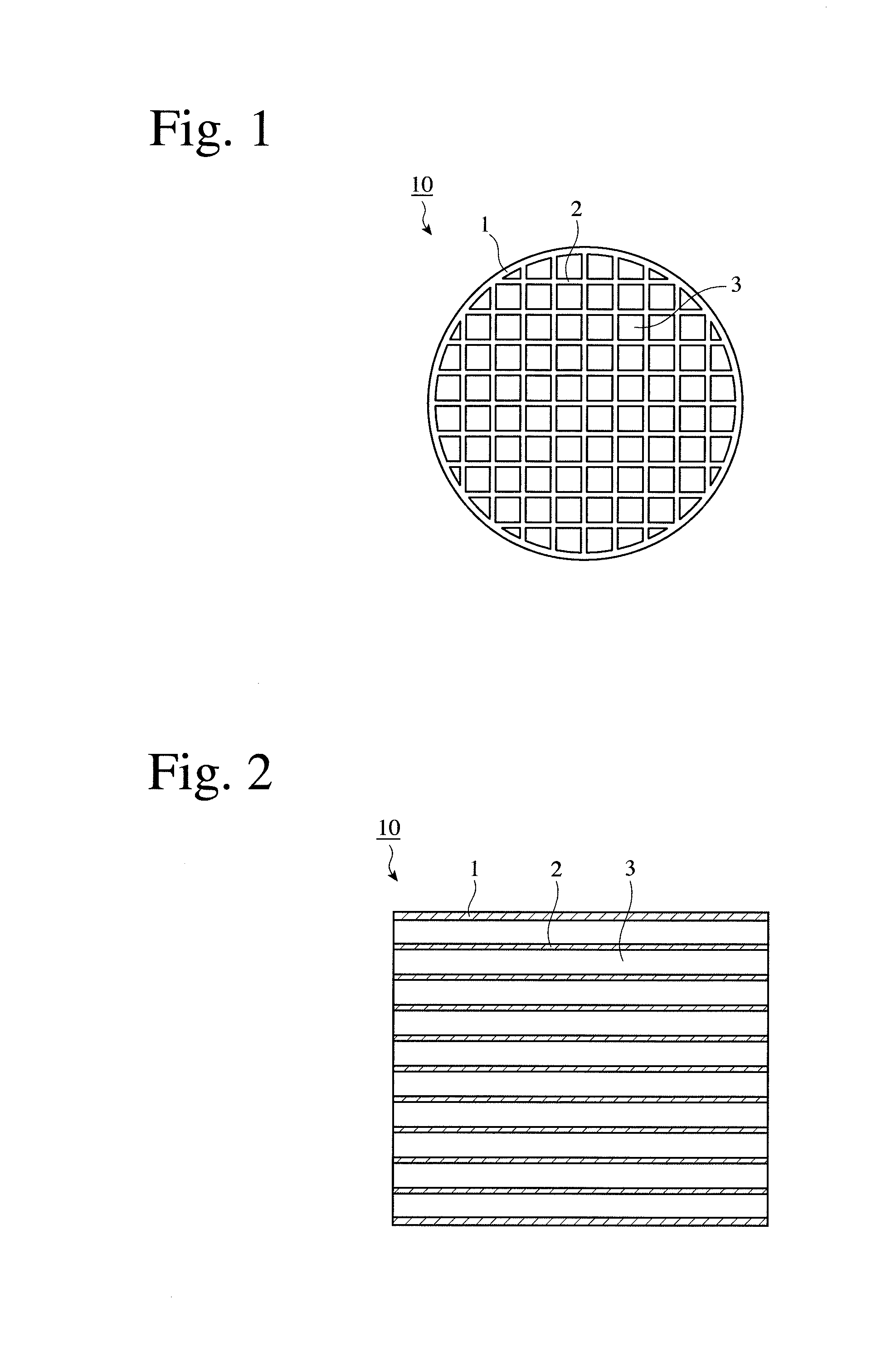
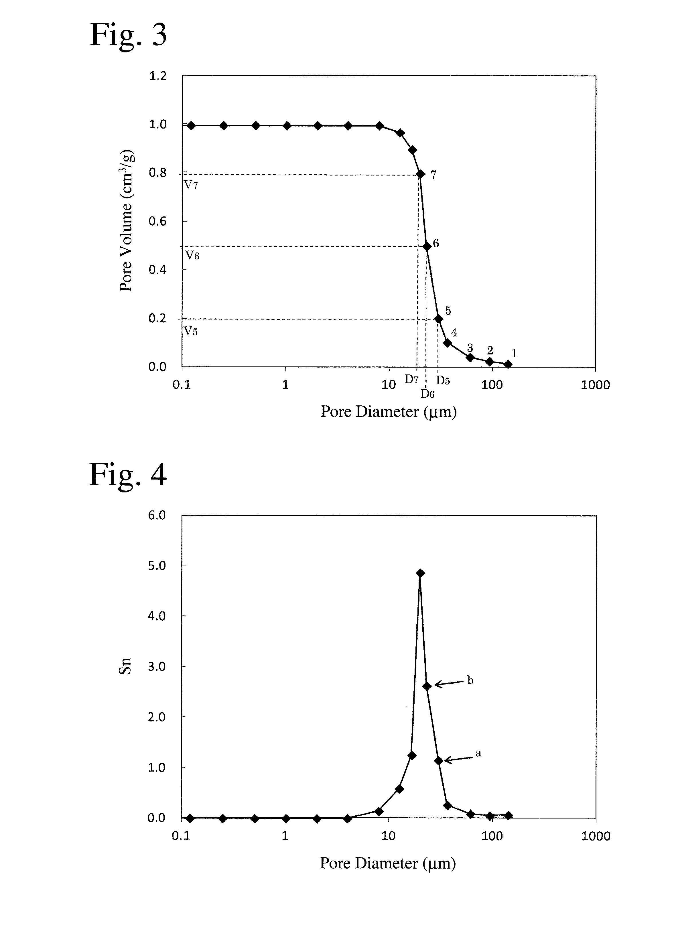
A cordierite-type ceramic honeycomb structure having large numbers of flow paths partitioned by porous cell walls; the cell walls having (a) porosity of more than 65% and 75% or less, (b) in a pore diameter distribution measured by mercury porosimetry, (i) a pore diameter d10 at a cumulative pore volume corresponding to 10% of the total pore volume being less than 50 μm, a pore diameter (median pore diameter) d50 at 50% being 18-27 μm, a pore diameter d90 at 90% being 10 μm or more, and (d10−d90)/d50 being 2.3 or less; (ii) σ[=log(d20)−log(d80)] being 0.25 or less, wherein σ represents the difference between a logarithm of a pore diameter d20 at a cumulative pore volume corresponding to 20% of the total pore volume and a logarithm of a pore diameter d80 at a cumulative pore volume corresponding to 80% of the total pore volume; and (iii) the maximum of the inclination Sn=−(Vn−Vn-1)/[log(dn)−log(dn-1)] of a curve of a cumulative pore volume to a pore diameter being 3 or more, wherein dn and Vn are respectively a pore diameter and a cumulative pore volume at an n-th measurement point, and dn-1 and Vn-1 are respectively a pore diameter and a cumulative pore volume at a (n−1)-th measurement point.
Description
FIELD OF THE INVENTION[0001]The present invention relates to a cordierite-type ceramic honeycomb structure used for a carrier carrying a catalytic material for removing harmful substance from exhaust gases of diesel engines, gasoline engines, etc., particularly used for a carrier carrying a catalytic material for removing nitrogen oxide.BACKGROUND OF THE INVENTION[0002]Because exhaust gases discharged from internal engines such as diesel engines, gasoline engines, etc. contain nitrogen oxide (NOx) and particulate matter (PM), harmful substances, exhaust pipes of the internal engines are provided with units for removing particulate matter, and units for removing nitrogen oxide. The nitrogen-oxide-removing units include an urea-SCR catalyst, in which urea injected into an exhaust pipe is turned to ammonia, which is reacted with nitrogen oxide in the exhaust gas to remove oxygen therefrom, thereby reducing nitrogen oxide to nitrogen, and thus removing nitrogen oxide from the exhaust ga...
Claims
Login to View More Application Information
Patent Timeline
 IPC IPC(8): B01D46/24B01J35/04C04B38/00F01N3/28B01D53/94
CPCB01D46/2429F01N3/2828B01D53/9418B01D2046/2437B01J35/04B01D2046/2496B01D2046/2433C04B38/0006B01D2251/208B01D2255/1021B01D2255/9202B01D2255/9205B01D2258/012B01J23/42C04B16/082C04B2111/0081B01D46/24492B01D46/24491B01D46/2498C04B35/195C04B38/0054C04B38/0074C04B38/067C04B20/1055B01D46/2484B01D46/247B01D2255/915B01J29/70B01J37/0018B01J37/08B28B3/20B28B2003/203C04B35/66C04B38/06
InventorOKAZAKI, SHUNJI
OwnerHITACHI METALS LTD